NCP1236
V
HV
V
HV(stop)
time
t
wd
t
wd
t
wd
Peak
detector
Reset
time
I
OPC
Sample
Sample
Reset
Sample
t
HV
time
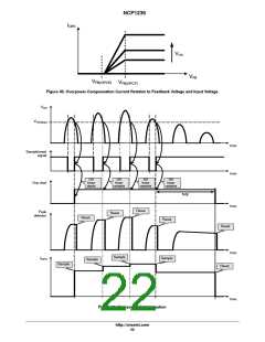
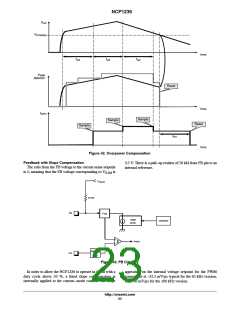
Figure 42. Overpower Compensation
Feedback with Slope Compensation
The ratio from the FB voltage to the current sense setpoint
is 5, meaning that the FB voltage corresponding to V
3.5 V. There is a pull−up resistor of 20 kW from FB pin to an
internal reference.
is
ILIM
V
FB(ref)
20 kW
FB
K
FB
slope
comp.
Oscillator
+
PWM
−
blanking
CS
t
LEB
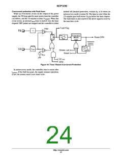
Figure 43. FB Circuitry
In order to allow the NCP1236 to operate in CCM with a
duty cycle above 50 %, a fixed slope compensation is
internally applied to the current−mode control. The slope
appearing on the internal voltage setpoint for the PWM
comparator is −32.5 mV/ms typical for the 65 kHz version,
and −50 mV/ms for the 100 kHz version.
http://onsemi.com
23

 ONSEMI [ ONSEMI ]