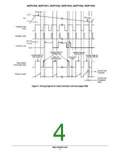
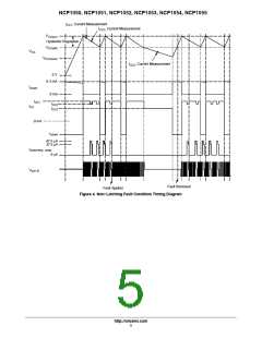
NCP1050, NCP1051, NCP1052, NCP1053, NCP1054, NCP1055
ELECTRICAL CHARACTERISTICS (V = 8.0 V, for typical values T = 25°C, for min/max values, T is the operating junction
CC
J
J
temperature range that applies (Note 3), unless otherwise noted.)
Characteristics
Symbol
Min
Typ
Max
Unit
POWER SWITCH CIRCUIT
Power Switch Circuit On−State Resistance
R
W
DS(on)
NCP1050, NCP1051, NCP1052 (I = 50 mA)
D
T = 25°C
T = 125°C
J
−
−
22
42
30
55
J
NCP1053, NCP1054, NCP1055 (I = 100 mA)
D
T = 25°C
T = 125°C
J
−
−
10
23
15
28
J
Power Switch Circuit & Startup Breakdown Voltage
V
700
−
−
V
(BR)DS
(I
D(off)
= 100 m A, T = 25°C)
A
Power Switch Circuit & Startup Circuit Off−State Leakage Current
(V = 650 V) T = 25°C
I
m
A
DS(off)
−
−
25
15
40
80
DS
J
(V = 650 V) T = 125°C
DS
J
Switching Characteristics (R = 50 W, V set for I = 0.7 I
)
ns
L
DS
D
Iim
Turn−on Time (90% to 10%)
Turn−off Time (10% to 90%)
t
on
t
off
−
−
20
10
−
−
CURRENT LIMIT AND THERMAL PROTECTION
Current Limit Threshold (T = 25°C) (Note 6)
I
lim
mA
J
NCP1050
NCP1051
NCP1052
NCP1053
NCP1054
NCP1055
93
100
200
300
400
530
680
107
214
321
428
567
728
186
279
372
493
632
2
2
Conversion Power Deviation (T = 25°C) (Note 7)
I f
−
0
10
%A Hz
J
OSC
Propagation Delay, Current Limit Threshold to Power Switch Circuit Output
NCP1050, NCP1051, NCP1052
NCP1053, NCP1054, NCP1055
t
ns
PLH
−
−
135
160
−
−
Thermal Protection (V = 8.6 V) (Note 3, 4, 5)
°C
CC
Shutdown (Junction Temperature Increasing)
Hysteresis (Junction Temperature Decreasing)
T
T
140
−
160
75
−
−
sd
H
STARTUP CONTROL
Startup/V Regulation
V
CC
Startup Threshold/V Regulation Peak (V Increasing)
V
V
8.0
7.0
−
8.5
7.5
1.0
9.0
8.0
−
CC
CC
CC(on)
Minimum Operating/V Valley Voltage After Turn−On
CC
CC(off)
V
H
Hysteresis
Undervoltage Lockout Threshold Voltage, V Decreasing
V
4.0
4.5
5.0
V
CC
CC(reset)
Startup Circuit Output Current (Power Switch Circuit Output = 40 V)
I
mA
start
V
CC
= 0 V
T = 25°C
T = −40 to 125°C
J
5.4
4.5
6.3
−
7.2
8.0
J
V
CC
= V
− 0.2 V
CC(on)
T = 25°C
T = −40 to 125°C
J
4.6
3.5
5.6
−
6.6
7.0
J
Minimum Start−up Drain Voltage (I
= 0.5 mA, V = V
− 0.2 V)
V
start(min)
−
13.4
20
V
start
CC
CC(on)
Output Fault Condition Auto Restart
(V Capacitor = 10 m F, Power Switch Circuit Output = 40 V)
CC
Average Switching Duty Cycle
Frequency
D
f
−
−
6.0
3.5
−
−
%
Hz
rst
rst
3. Tested junction temperature range for the NCP105X series:
T
low
= −40°C
T
high
= +125°C
4. Maximum package power dissipation limits must be observed.
5. Guaranteed by design only.
6. Adjust di/dt to reach I in 4.0 m sec.
lim
7. Consult factory for additional options including test and trim for output power accuracy.
http://onsemi.com
8

 ONSEMI [ ONSEMI ]