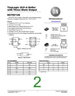
NC7SV126
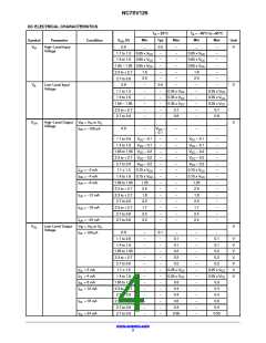
DC ELECTRICAL CHARACTERISTICS (continued)
T
A
= 255C
Typ
−
T
= −405C to +855C
A
Min
Max
Min
Max
Symbol
Parameter
Condition
V
CC
(V)
Unit
I
Input Leakage
Current
V
V
= 3.6 V or GND
0.9 to 3.6
0.9 to 3.6
0
−
0.1
−
−
−
−
0.5
mA
IN
IN
I
3−State Output
Leakage Current
= 0 V to 3.6 V
−
−
−
−
−
−
0.5
0.5
0.9
0.5
0.5
0.9
mA
mA
mA
OZ
OUT
I
Power Off Leakage
Current
V
V
= 3.6 V or
= 3.6 V
OFF
IN
OUT
I
Quiescent Supply
Current
V
IN
= V or GND
0.9 to 3.6
CC
CC
Product parametric performance is indicated in the Electrical Characteristics for the listed test conditions, unless otherwise noted. Product
performance may not be indicated by the Electrical Characteristics if operated under different conditions.
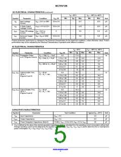
AC ELECTRICAL CHARACTERISTICS
T
A
= 25°C
Typ
17.6
6.3
T
= −405C to +855C
A
Min
−
Max
−
Min
Max
Symbol
Parameter
Condition
V
(V)
Unit
CC
t
t
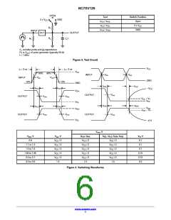
Propagation Delay,
A to Y (Figures 3 and 4)
0.9
−
−
−
−
−
−
−
−
−
−
−
−
−
−
−
−
−
−
−
ns
R = 1 MW, C = 15 pF
PLH, PHL
L
L
R = 2 kW, C = 15 pF
1.10 to 1.30
1.40 to 1.60
1.65 to 1.95
2.3 to 2.7
2.7 to 3.6
0.9
−
12.6
5.3
4.3
2.8
2.6
−
14.9
5.7
4.6
3.0
2.8
−
L
L
−
3.8
R = 500 W, C = 30 pF
−
3.0
L
L
−
2.1
−
1.8
t
t
t
Output Enable Time,
OE to Y
(Figures 3 and 4)
C = 30 pF
−
19.7
6.0
ns
ns
PZH, PZL
L
1
R = R = 1 kW
L
1.10 to 1.30
1.40 to 1.60
1.65 to 1.95
2.3 to 2.7
2.7 to 3.6
0.9
−
9.7
6.0
4.5
3.0
2.6
−
16.4
7.5
5.0
3.4
2.9
−
−
3.5
−
2.7
−
2.0
−
1.7
t
Output Disable Time,
OE to Y
(Figures 3 and 4)
C = 30 pF
−
10.3
4.9
PHZ, PLZ
L
1
R = R = 1 kW
L
1.10 to 1.30
1.40 to 1.60
1.65 to 1.95
2.3 to 2.7
2.7 to 3.6
−
9.5
5.5
5.6
4.2
3.9
14.0
7.0
5.8
5.0
4.2
−
3.3
−
3.0
−
2.5
−
2.9
CAPACITIVE CHARACTERISTICS
Symbol
Parameter
Input Capacitance
Output Capacitance
Power Dissipation Capacitance (Note 5)
Test Condition
Typical (T = 25°C)
Unit
pF
A
C
V
V
= 0 V
= 0 V
2.0
4.5
20
IN
CC
C
pF
OUT
CC
C
10 MHz, V = 0.9 to 3.6 V, V = 0 V or V
CC
pF
PD
CC
IN
5. C is defined as the value of the internal equivalent capacitance which is calculated from the operating current consumption without load.
PD
Average operating current can be obtained by the equation I
) = C ꢀ V ꢀ f + I . C is used to determine the no−load dynamic
CC(OPR
PD CC in CC PD
2
power consumption: P = C ꢀ V
ꢀ f + I ꢀ V
.
D
PD
CC
in
CC
CC
www.onsemi.com
4

 ONSEMI [ ONSEMI ]