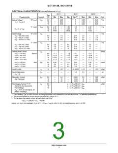
MC14514B, MC14515B
COMPLEX DATA ROUTING
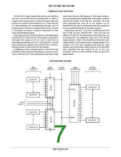
Two MC14512 eight–channel data selectors are used here
times faster then the shift frequency of the input registers,
the most significant bit (MSB) from each register could be
selected for transfer to the data bus. Therefore, all of the
most significant bits from all of the registers can be
transferred to the data bus before the next most significant
bit is presented for transfer by the input registers.
Information from the 3–state bus is redistributed by the
MC14514B four–bit latch/decoder. Using the four–bit
address, D1 thru D4, the information on the inhibit line can
be transferred to the addressed output line to the desired
output registers, A thru P. This distribution of data bits to the
output registers can be made in many complex patterns. For
example, all of the most significant bits from the input
registers can be routed into output register A, all of the next
most significant bits into register B, etc. In this way
horizontal, vertical, or other methods of data slicing can be
implemented.
with the MC14514B four–bit latch/decoder to effect a
complex data routing system. A total of 16 inputs from data
registers are selected and transferred via a 3–state data bus
to a data distributor for rearrangement and entry into 16
output registers. In this way sequential data can be re–routed
or intermixed according to patterns determined by data
select and distribution inputs.
Data is placed into the routing scheme via the eight inputs
on both MC14512 data selectors. One register is assigned to
each input. The signals on A0, A1, and A2 choose one of
eight inputs for transfer out to the 3–state data bus. A fourth
signal, labelled Dis, disables one of the MC14512 selectors,
assuring transfer of data from only one register.
In addition to a choice of input registers, 1 thru 16, the rate
of transfer of the sequential information can also be varied.
That is, if the MC14512 were addressed at a rate that is eight
DATA ROUTING SYSTEM
INPUT
REGISTERS
DATA
TRANSFER
3–STATE
DATA BUS
DATA
DISTRIBUTION
OUTPUT
REGISTERS
DIS
D0
D1
D2
Q
REGISTER 1
REGISTER 8
D1 D2 D3 D4
S0
D3
D4
REGISTER A
STROBE
S1
S2
D5
D6
S3
D7
S4
A0 A1 A2
S5
S6
DATA
S7
SELECT
S8
S9
S10
S11
S12
S13
S14
S15
A0 A1 A2
D0
D1
D2
D3
D4
D5
D6
D7
Q
REGISTER 9
REGISTER 16
INHIBIT
REGISTER P
DIS
http://onsemi.com
7

 ONSEMI [ ONSEMI ]