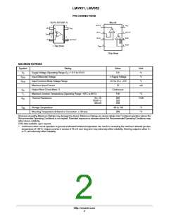
LMV931, LMV932
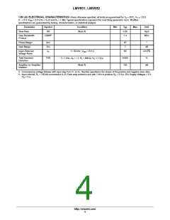
2.7V AC ELECTRICAL CHARACTERISTICS Unless otherwise specified, all limits are guaranteed for T = 25°C, V+ = 2.7 V,
A
V− = 0 V, V
= 2.0V ,Vo = V+/2 and R > 1 MW. Typical specifications represent the most likely parametric norm. Min/Max
CM
L
specifications are guaranteed by testing, characterization, or statistical analysis.
Parameter
Slew Rate
Symbol
SR
Condition
Min
Typ
0.4
1.4
Max
Unit
V/uS
MHz
(Note 6)
Gain Bandwidth
Product
GBWP
Phase Margin
Gain Margin
m
70
7.5
57
°
Gm
dB
Input−Referred
Voltage Noise
e
n
f = 50 kHz, V
= 1.0 V
nV/√Hz
CM
Total Harmonic
Distortion
THD
f = 1 kHz, A = +1, R = 600 W, V = 1 V
0.022
123
%
V
L
O
PP
Amplifier−to−Amplifier
Isolation
(Note 7)
dB
6. Connected as voltage follower with input step from V− to V+. Number specified is the slower of the positive and negative slew rates.
7. Input referred, R = 100 kW connected to V+/2. Each amp excited in turn with 1 kHz to produce V = 3 V . (For Supply Voltages < 3 V,
L
O
PP
V
O
= V+).
http://onsemi.com
6

 ONSEMI [ ONSEMI ]