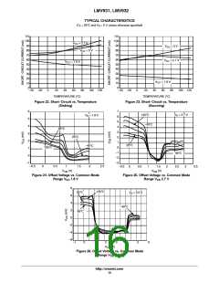
LMV931, LMV932
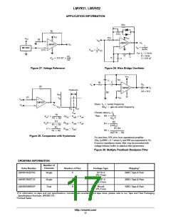
APPLICATION INFORMATION
50 k
R1
5.0 k
V
CC
10 k
V
CC
V
CC
R2
−
V
ref
−
V
O
LMV931
V
O
LMV931
+
1
f
+
MC1403
+
O
1
2
2pRC
V
+
V
2.5 V
ref
CC
For: f = 1.0 kHz
o
R = 16 kW
C = 0.01 mF
R
R1
R2
C
R
V
+ 2.5 V(1 )
)
C
O
Figure 27. Voltage Reference
Figure 28. Wien Bridge Oscillator
V
CC
R3
C
C
R1
−
C
V
in
O
R2
V
LMV931
O
Hysteresis
+
CO = 10 C
R2
V
OH
R1
V
ref
V
O
+
V
ref
LMV931
Given: f = center frequency
o
V
O
V
in
−
V
OL
A(f ) = gain at center frequency
o
V
inL
V
inH
Choose value f , C
V
o
ref
Q
R1
Then : R3 +
V L +
(V * V
) V
) V
in
OL
ref)
ref)
ref
ref
pf
C
R1 ) R2
R1
O
R3
2 A(f )
V H +
(V
(V
* V
* V
R1 +
R2 +
in
OH
R1 ) R2
O
R1
R1 R3
H +
)
OH
OL
R1 ) R2
2
4Q R1 * R3
Figure 29. Comparator with Hysteresis
For less than 10% error from operational amplifier,
((Q f )/BW) < 0.1 where f and BW are expressed in Hz.
O
O
o
If source impedance varies, filter may be preceded with
voltage follower buffer to stabilize filter parameters.
Figure 30. Multiple Feedback Bandpass Filter
ORDERING INFORMATION
Number of
Channels
†
Order Number
Number of Pins
Package Type
Shipping
LMV931SQ3T2G
Single
5
SC70−5
(Pb−Free)
3000 / Tape & Reel
LMV931SN3T1G
LMV932DMR2G*
Single
Dual
5
8
TSOP−5
3000 / Tape & Reel
4000 / Tape & Reel
(Pb−Free)
Micro8
(Pb−Free)
†For information on tape and reel specifications, including part orientation and tape sizes, please refer to our Tape and Reel Packaging
Specifications Brochure, BRD8011/D.
*Consult Sales.
http://onsemi.com
17

 ONSEMI [ ONSEMI ]