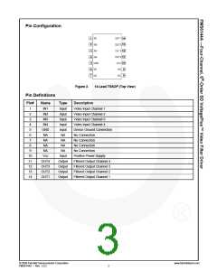
Pin Configuration
Figure 2.
14-Lead TSSOP (Top View)
Pin Definitions
Pin#
1
Name
IN1
Type
Input
Input
Input
Input
Input
NA
Description
Video Input Channel 1
Video Input Channel 2
Video Input Channel 3
Video Input Channel 4
Device Ground Connection
No Connection
2
IN2
3
IN3
4
IN4
5
GND
NA
6
7
NA
NA
No Connection
8
NA
NA
No Connection
9
NA
NA
No Connection
10
11
12
13
14
Vcc
Input
Output
Output
Output
Output
Positive Power Supply
Filtered Output Channel 4
Filtered Output Channel 3
Filtered Output Channel 2
Filtered Output Channel 1
OUT4
OUT3
OUT2
OUT1
© 2009 Fairchild Semiconductor Corporation
FMS6144A • Rev. 1.0.2
www.fairchildsemi.com
2

 ONSEMI [ ONSEMI ]