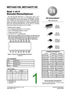
MC74AC139, MC74ACT139
E
A A
0 1
DECODER a
O
0
O
1
O
2
O
3
E
A A
0 1
DECODER b
O
0
O O O
1 2 3
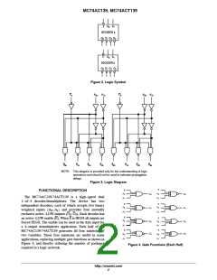
Figure 2. Logic Symbol
E
a
A
0a
A
1a
E
b
A
0b
A
1b
0
0a
0
1a
0
2a
0
3a
0
0b
0
1b
0
2b
0
3b
NOTE: This diagram is provided only for the understanding of logic
operations and should not be used to estimate propagation
delays.
Figure 3. Logic Diagram
E
E
FUNCTIONAL DESCRIPTION
A
A
O
O
O
0
1
0
1
0
0
The MC74AC139/74ACT139 is a high−speed dual
1−of−4 decoder/demultiplexer. The device has two
independent decoders, each of which accepts two binary
A
A
E
E
A
A
0
0
O
1
1
weighted inputs (A −A ) and provides four mutually
0
1
A
A
1
1
exclusive active−LOW outputs (O −O ). Each decoder has
0
3
E
E
an active−LOW enable (E). When E is HIGH all outputs are
forced HIGH. The enable can be used as the data input for
a 4−output demultiplexer application. Each half of the
MC74AC139/74ACT139 generates all four minterms of
two variables. These four minterms are useful in some
applications, replacing multiple gate functions as shown in
Figure 4, and thereby reducing the number of packages
required in a logic network.
A
0
O
O
A
O
O
2
0
1
2
A
A
1
E
E
A
3
A
3
0
1
0
1
A
A
Figure 4. Gate Functions (Each Half)
http://onsemi.com
2

 ONSEMI [ ONSEMI ]