WL/WLM
Indicators
Indicator Covers
Indicator
The indicator covered if outsert molded
from diecast aluminum and has
outstanding sealing properties.
The indicator is either a neon lamp or
an LED. Models with LED indicators
have a built-in rectifier stack, so it is not
necessary to change the polarity.
Indicator Windows
Operation (i.e., light-ON when operating
or light-ON when not operating) depends
on whether a neon lamp or LED is used.
Contact Spring
The built-in switch's terminal screws
are used to connect the indicator
terminal. Since the connection spring
(coil spring) is used for this connection,
it will not be necessary to connect the
indicator terminal. When a ground
terminal is provided however, a lead
wire must be used.
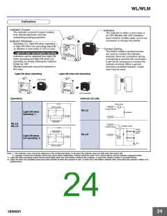
Light-ON when Operating/Not Operating
Indicators can be switched from light-ON
when operating and light-ON when not
operating, by simply rotating the indicator
holder by 180°.
(Molded terminals cannot be switched in
this way.)
Light-ON when Operating
Light-ON when Not Operating
LED at top
LED at bottom
Operation
Internal Circuits
Power
Neon lamp
Built-in switch
Za
Contact spring
Resistor
4
1
3
2
WL-LE
Light-ON when
operating *1
Load
Internal circuits
WL-LE
WL-LD
Rectifier stack
Contact spring
Power
Rated
current
diode
Resistor
Resistor
Internal circuits
WL-LD
Za
Light-ON when
not operating *2
Zener
diode
Load
4
1
3
2
LED
Built-in switch
Note: 1. The indicator cover cannot be replaced on the molded terminals. In all cases the indicator does not light when the load is ON.
2. Leakage current from indicator circuit may cause load's malfunction. Please check the load's OFF current before use the indicator-equipped switch.
*1. Light-ON when operating means that the lamp lights when the Limit Switch contacts (NC) release, or when the actuator rotates or is pushed down.
*2. Light-ON when not operating means the lamp remains lit when the actuator is free, or when the Limit Switch contacts (NO) close when the actuator rotates or is
pushed down.
24

 OMRON [ OMRON ELECTRONICS LLC ]