■ Characteristics
Contact resistance
100 mΩ max.
Operate time
AC: 20 ms max.
DC: 30 ms max.
Release time
20 ms max.(40 ms max. for built-in diode models)
Max. operating frequency
Mechanical: 18,000 operations/hr (no load)
Electrical:1,800 operations/hr (at rated load)
Insulation resistance
Dielectric strength
100 MΩ min. (at 500 VDC)
2,500 VAC 50/60 Hz for 1 min. between coil and contacts
1,000 VAC 50/60 Hz for 1 min. between contacts of same polarity and terminals of the same polarity
2,500 VAC 50/60 Hz for 1 min. between current-carrying parts, non-current-carrying parts, and opposite
polarity
Insulation method
Basic insulation
Impulse withstand voltage
4.5 kV between coil and contacts (with 1.2 × 50 μs impulse wave)
3.0 kV between contacts of different polarity (with 1.2 × 50 μs impulse wave)
Pollution degree
3
Rated insulation voltage
Vibration resistance
250 V
Destruction:10 to 55 Hz, 1.5 mm double amplitude
Malfunction:10 to 55 Hz, 1.0 mm double amplitude
Destruction:1,000 m/s2 (approx. 100 G)
Malfunction:100 m/s2 (approx. 10 G)
Mechanical: 5,000,000 operations min.
Electrical:100,000 operations min.
Shock resistance
Life expectancy
10 mA at 1 VDC P level: λ60=0.1 x 10⁻⁶ / ops
Operating: –40 to 60°C (with no icing or condensation)
Operating: 5% to 85%
Min. permissible load
Ambient temperature
Ambient humidity
Weight
Approx. 90 g
Note: 1. The values given above are initial values.
2. Ambient temperature of models with LED indicator is −25 to 60°C.
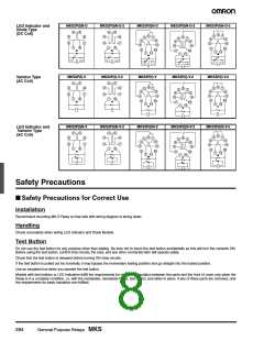
■ Approved Standards
UL Recognized (File No. E41515) - - Ambient Temp. = 40°C
IEC Standard/TUV Certification: IEC61810-1
(Certification No. R50104853)
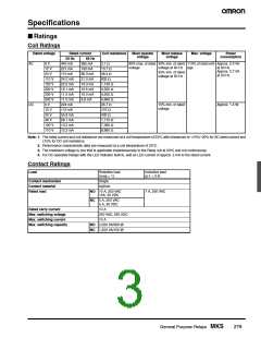
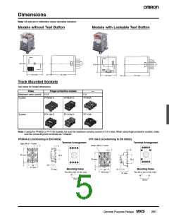
Coil ratings
Contact ratings
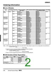
Operations
Coil ratings
6, 12, 24, 48, N.O.
100, 110 VDC contact 10 A, 30 V DC (Resistive)
6, 12, 24, 100,
110, 200, 220,
240 VAC
Contact ratings
10 A, 250 V AC 50/60 Hz (Resistive) 100,000
Operations
6 to 110 VDC N.O.
10 A, 250 V AC 50/60 Hz (Resistive) 100,000
6 to 240 VAC contact 10 A, 30 V DC (Resistive)
7 A, 250 V AC 50/60 Hz (General Use)
N.C.
10 A, 250 V AC 50/60 Hz (Resistive) 100,000
7 A, 250 V AC 50/60 Hz (General Use)
contact 10 A, 30 V DC (Resistive)
7 A, 250 V AC 50/60 Hz (General Use)
N.C.
5 A, 250 V AC 50/60 Hz (Resistive)
contact 5 A, 30 V DC (Resistive)
7 A, 250 V AC 50/60 Hz (General Use)
100,000
Note: 10A UL ratings are with no load on the other contact set.
Note: Maximum carrying current per TUV Certification is 9 A when
new MK-S relays are mounted in PF083A-E or PF113A-E
Sockets.
CSA Certified by
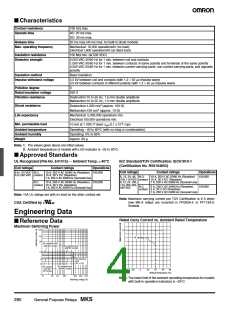
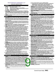
Engineering Data
Rated Carry Current vs. Ambient Rated Temperature
■ Reference Data
Maximum Switching Power
100
10
50
UL derating curve
30
DC resistive load
with NO contact
AC resistive load
with NO contact
5
10
AC inductive
load
(p.f. = 0.4)
5
3
AC resistive load
with NC contact
DC resistive
load with
NC contact
0
−40
−20
0
20
40
60
80
Ambient temperature (°C)
1
10
30
50
100
300 500 1.000
Note: The lower limit of the ambient operating temperature for models
with built-in operation indicators is −25°C.
Switching voltage (V)
280
General Purpose Relays MKS

 OMRON [ OMRON ELECTRONICS LLC ]