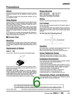
Precautions
Wiring
Relays Mounted
Be sure to turn OFF the power when wiring the Unit and do not touch
the charged terminals of the Unit. Otherwise, an electric shock may
result.
G6B-4@@ND standard:
G6B-1114P-FD-US
G6B-1174P-FD
G6B-4@@ND long life:
G6B-4@@ND high reliability: G6B-1184P-US
Replacement is not possible for G6B-48BND.
Do not apply overvoltage to the input terminals. Otherwise, the Unit
may malfunction or burn.
Wiring
Relay Models
Be sure to connect the input terminals with the correct polarity.
Do not connect the Unit to loads exceeding the rated switching power
(switching voltage or current). Otherwise, faulty insulation, contact
weld, or faulty contact of Relays, or damage to Relays may result, or
the Relays may malfunction or burn.
The life of Relays varies with the switching condition. Test the Relays
under the actual operating conditions before using the Relays within
the permissible switching frequency. The use of deteriorated Relays
may result in the faulty insulation of the Relays or cause the Relays
to burn.
Coil Voltage
Be sure not to impose voltage exceeding the permissible voltage on
the coil continuously.
Do not use the relays when other inductive loads are connected in
parallel with the coil input or when there are surges during power
supply because the built-in diodes used to absorb surge may be
destroyed.
Do not use the Unit in locations with inflammable gas. Otherwise, a
fire or explosion due to the heat of the Relays or sparks from the
Relays may result when they are switched.
Do Not Use the Following Circuit
■ Correct Use
Coil surge current
absorption diode
Inductive load
G6B Coil
Mounting
Heat generated by the relays must be considered when gang-mount-
ing. Space must be provided between the relays or other methods
must be taken to maintain the relays’ ambient temperature at 55 °C
or lower.
Handling
Do not drop, shock, or vibrate the Unit excessively. Otherwise, dam-
age to the Unit may result or the Unit may malfunction.
Replacement of Relays
Make sure that all the Relays are properly mounted before use.
G6B-4@@ND
Use the P6B-Y1 Removal Tool as shown in the following diagram.
Screw Tightening Torque
Tighten each terminal screw to a torque of 0.78 to 1.18N·m.
Tighten each mounting screw to a torque of 0.59 to 0.98 N·m.
Installation Environment
Do not install the Unit in the following locations. Otherwise, damage
to the Unit may result or the Unit may malfunction.
Locations with direct sunlight.
Locations with an ambient temperature range not within 0°C to 55°C.
Locations with rapid temperature changes resulting in condensation
or locations with relative humidity ranges not within 10% to 90%.
Locations with corrosive or inflammable gas.
Locations with excessive dust, salinity, or metal powder.
Locations with vibration or shock affecting the Unit.
Locations with water, oil, or chemical sprayed on the Unit.
Be sure to turn OFF the power to the Unit before replacing a Relay.
Relays must be inserted straight onto the socket connector pins to
ensure proper connection.
G6B-48BND models (high reliability) are connected directly to
boards to increase reliability and the relays are thus not replaceable.
If relay replacement is necessary, use the P6BF-4BND Terminal
Sockets together with the G6B-1184P Mini Relays. P6BF-4BND Ter-
minal Sockets are equipped with relay replacement sockets.
Disassembly, Repair, and Modification
Do not disassemble, repair, or modify the Unit. Otherwise, an electric
shock may result or the Unit may malfunction.
Do not mount Relays that are different to one another in voltage.
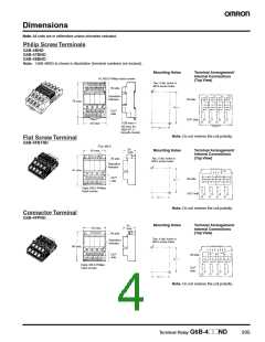
ALL DIMENSIONS SHOWN ARE IN MILLIMETERS.
To convert millimeters into inches, multiply by 0.03937. To convert grams into ounces, multiply by 0.03527.
In the interest of product improvement, specifications are subject to change without notice.
Cat. No. J098-E1-02A
Terminal Relay G6B-4@@ND
207

 OMRON [ OMRON ELECTRONICS LLC ]