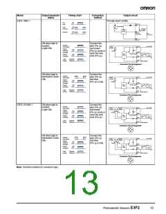
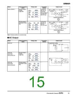
Model
Output transistor
status
Timing chart
Connection
method
Output circuit
Brown
E3F2-LS10C4-@
ON when light is
incident.
(Light-ON)
Connect the
10 to 30 VDC
Load
Output
indicator
Stability
indicator*
1
Incident
Interrupted
2
pink (Pin
)
Orange
Green
100 mA
max.
and brown
Output
indicator
(red)
Black
Blue
Pink
ON
OFF
4
3
2
1
(Pin ) cords or
open the pink
Main
circuit
Output
transistor
ON
OFF
0 V
2
Z : V = 36 V
D Z
cord (Pin ).
Mode selection
Load
(relay)
Operate
Release
Connector Pin Arrangement
1
2
4
3
ON when light is
interrupted. (Dark-
ON)
Connect the
Brown
10 to 30 VDC
Load
Output
indicator
Stability
indicator*
1
Incident
Interrupted
2
pink (Pin
and blue
3
)
Orange
Green
100 mA
max.
Output
indicator
(orange)
Black
Blue
Pink
ON
OFF
4
3
2
(Pin ) cords.
Main
circuit
Output
transistor
ON
OFF
0 V
Z : V = 36 V
D Z
Mode selection
Load
(relay)
Operate
Release
Connector Pin Arrangement
1
2
4
3
Note: Terminal numbers for connector type.
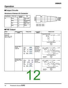
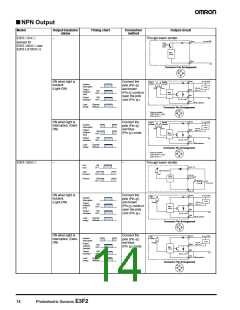
■ AC Output
Model
Output transistor
status
Timing chart
Connection
method
Output circuit
E3F2-3LZ
–
–
–
–
Through-beam emitter
Brown
Power
indicator
(red)
Main
circuit
24 to 240 VAC
Blue
E3F2-3Z1
E3F2-R2Z1
E3F2-DS10Z1-N
ON when light is
incident.
(Light-ON)
Incident
Interrupted
Output
indicator
(red)
ON
OFF
Output
transistor
ON
OFF
Brown
Light
indicator
200 mA
max.
Black
Load
(relay)
Operate
Release
Load
Red
Main
circuit
24 to 240 VAC
E3F2-3Z2
E3F2-R2Z2
E3F2-DS10Z2-N
ON when light is
interrupted. (Dark-
ON)
–
Blue
Incident
Interrupted
Output
indicator
(red)
ON
OFF
Output
ON
transistor
OFF
Load
(relay)
Operate
Release
Photoelectric Sensors E3F2
15

 OMRON [ OMRON ELECTRONICS LLC ]