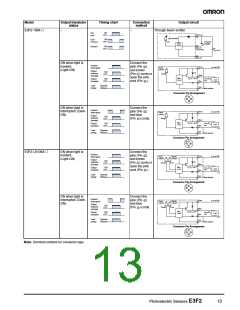
Model
Output transistor
status
Timing chart
Connection
method
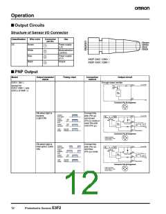
Output circuit
Through-beam emitter
E3F2-10B4-@
–
–
Test
ON
input
OFF
Light
emission
ON
OFF
Red
Indicator
ON
OFF
ON when light is
incident.
(Light-ON)
Connect the
Incident
Interrupted
2
pink (Pin
)
Brown
10 to 30 VDC
Output
indicator
1
and brown
Output
indicator
(orange)
ON
OFF
Z
D
Orange
1
(Pin ) cords or
open the pink
Black
Blue
Pink
4
3
2
Main
circuit
Z
D
: V = 36 V
Z
Output
transistor
ON
OFF
100 mA
max.
Load
0 V
2
cord (Pin ).
Load
(relay)
Operate
Release
Mode selection
Connector Pin Arrangement
1
2
4
3
ON when light is
interrupted. (Dark-
ON)
Connect the
Incident
Interrupted
2
Brown
pink (Pin
and blue
3
)
10 to 30 VDC
Output
indicator
1
Output
indicator
(orange)
ON
OFF
Orange
(Pin ) cords.
Black
Blue
Pink
4
3
2
Main
circuit
Z : V = 36 V
D Z
100 mA
max.
Output
transistor
ON
OFF
Load
0 V
Load
(relay)
Operate
Release
Mode selection
Connector Pin Arrangement
1
2
4
3
E3F2-LS10B4-@
ON when light is
incident.
(Light-ON)
Connect the
Incident
Interrupted
2
pink (Pin
)
Brown
10 to 30 VDC
Output
indicator
Stability
indicator*
1
and brown
Output
indicator
(orange)
ON
OFF
Z
D
Orange
Green
1
(Pin ) cords or
open the pink
Black
Blue
Pink
4
3
2
Main
circuit
Z : V = 36 V
D Z
Output
transistor
ON
OFF
100 mA
max.
Load
0 V
2
cord (Pin ).
Load
(relay)
Operate
Release
Mode selection
Connector Pin Arrangement
1
2
4
3
ON when light is
interrupted. (Dark-
ON)
Connect the
Incident
Interrupted
2
Brown
pink (Pin
and blue
3
)
10 to 30 VDC
Output
indicator
Stability
indicator*
1
Output
indicator
(orange)
ON
OFF
Orange
Green
(Pin ) cords.
Black
Blue
Pink
4
3
2
Main
circuit
Z : V = 36 V
D Z
100 mA
max.
Output
transistor
ON
OFF
Load
0 V
Load
(relay)
Operate
Release
Mode selection
Connector Pin Arrangement
1
2
4
3
Note: Terminal numbers for connector type.
Photoelectric Sensors E3F2
13

 OMRON [ OMRON ELECTRONICS LLC ]