D4B-@N
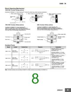
Application Precaution
Operating section
(on back of Head)
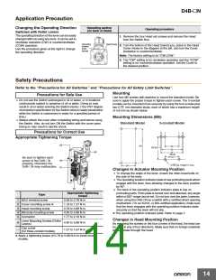
Changing the Operating Direction
Switches with Roller Levers
Operating procedure
The operating direction of the lever can be easily
changed without using any tools. It can be set to
clockwise operation (CW) or counterclockwise
(CCW) operation.
Use the procedure given at the right to change
the operating direction.
1. Remove the four Head set screws and remove the Head
from the Switch Box.
Operating
position
mark
Head Cover
2. Turn the bottom of the Head toward you, press in the Head
Cover shown in the diagram at the left, and turn the Cover
clockwise or counterclockwise.
(arrow)
Note: The factory setting is for “CW.CCW.”
3. The “CW” setting is for clockwise operation and the “CCW”
setting is for counterclockwise operation. Set the Cover to
the desired position.
Safety Precautions
Refer to the “Precautions for All Switches” and “Precautions for All Safety Limit Switches”.
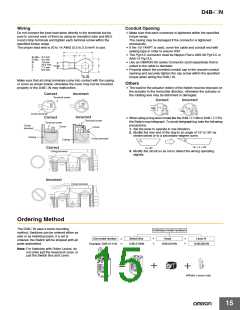
Mounting
Precautions for Safe Use
Use four M5 screws with washers to mount the standard model. Be
• Do not use the Switch submerged in oil or water, or in locations
continuously subject to splashes of oil or water. Doing so may
result in oil or water entering the Switch interior. (The IP67 degree
of protection specification for the Switch refers to water penetration
while the Switch is submersed in water for a specified period of
time.)
• Always attach the cover after completing wiring and before using
the Switch. Also, do not turn ON the Switch with the cover open.
Doing so may result in electric shock.
sure to apply the proper torque to tighten each screw. The 3-conduit
models can be mounted more securely by using the four screws plus
two 5−0.105 mm diameter studs, each of which has a maximum height
of 4.8 mm as shown below.
Mounting Dimensions (M5)
3-conduit Model
Standard Model
Precautions for Correct Use
Appropriate Tightening Torque
(3)
60
30
59.3 0.1
40
(6)
42
Studs
27 0.1
Be sure to tighten each
(4)
screw of the D4B-@N
properly, otherwise the
−0.05
5
dia. height: 5 max.
−0.15
30
D4B-@N may malfunction.
(1)
Changes in Actuator Mounting Position
• To change the angle of the lever, loosen the Allen-head bolts on
the side of the lever.
• The operating position indicator plate * has protruding parts which
engage with the lever, thus allowing changes to the lever position
by 90°.
(5)
(2)
• The back of the operating position indicator plate * has no
protruding parts. If this plate is turned over and attached, any angle
within a 360° range can be set. Do not turn over the plate, however,
when using the D4B-@N as a switch with a certified direct opening
mechanism. For an SUVA- or BIA-certified application, make sure
that the lever engages with the operating position indicator plate
securely so that the lever will not slip.
Appropriate tightening
torque
Type
1
2
3
4
5
M3.5 terminal screw
Cover mounting screw *
Head mounting screw
M5 body mounting screw
Connector
0.59 to 0.78 N·m
1.18 to 1.37 N·m
0.78 to 0.88 N·m
4.90 to 5.88 N·m
1.77 to 2.16 N·m
* The operating position indicator plate: Refer to page 7.
Changes in Head Mounting Position
By removing the screws on the four corners of the head, the head can
be reset in any of four directions. Make sure that no foreign materials
will penetrate through the head.
Lever Mounting Screws (Roller
Levers)
6
4.90 to 5.88 N·m
1.27 to 1.67 N·m
Cap screw
(for three-conduit models)
---
* Apply a tightening torque of 0.78 to 0.88 N·m to three-conduit
models.
14

 OMRON [ OMRON ELECTRONICS LLC ]