FEDL66517-01
1
Semiconductor
ML66517 Family
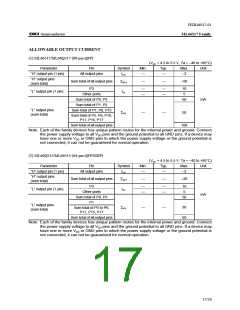
ELECTRICAL CHARACTERISTICS
DC Characteristics
(VDD = 4.5 to 5.5 V, Ta = –40 to +80°C)
Parameter
“H” input voltage
“H” input voltage
“L” input voltage
“L” input voltage
Symbol
VIH
Condition
—
Min.
0.44 VDD
0.80 VDD
–0.3
Typ.
—
—
—
—
Max.
VDD + 0.3
VDD + 0.3
0.16 VDD
0.2 VDD
—
—
—
—
0.4
0.8
0.4
1.0
0.4
0.8
1/–1
1/–250
15/–15
Unit
*1
*2 to *8
*1
VIL
—
*2 to *8
–0.3
IO = –400 µA
IO = –2.0 mA
IO = –200 µA
IO = –2.0 mA
IO = 3.2 mA
IO = 5.0 mA
IO = 3.2 mA
IO = 10.0 mA
IO = 1.6 mA
IO = 5.0 mA
VDD – 0.4
VDD – 0.6
VDD – 0.4
VDD – 0.6
—
“H” output voltage *1, *4, *5
“H” output voltage *2
—
—
—
—
—
—
—
—
—
—
—
—
VOH
V
“L” output voltage
“L” output voltage
“L” output voltage
*1, *5
*4
—
—
—
—
—
—
—
—
VOL
*2
Input leakage current*3, *7
Input current
Input current
Output leakage current
*1, *2, *4, *5
Pull-up resistance
Input capacitance
Output capacitance
*6
*8
IIH/IIL
ILO
VI =VDD/0 V
µA
VO =VDD/0 V
VI = 0 V
—
—
µA
kΩ
pF
± 10
Rpull
CI
CO
25
—
—
—
—
50
5
7
—
—
100
—
—
4
f = 1 MHz, Ta = 25°C
During A/D operation
When A/D is stopped
mA
µA
Analog reference supply current
IREF
10
*1: Applicable to P0
*2: Applicable to P1, P2, P6, P7, P8, P10, P11, P15, P17
*3: Applicable to P12
*4: Applicable to P3
*5: Applicable to P16
*6: Applicable to RES
*7: Applicable to EA, NMI, CLKSEL0, CLKSEL1
*8: Applicable to OSC0
Supply current
Symbol
IDD
Condition
f=25 MHz
f=25 MHz
Min.
—
Typ.
Max.
60
Unit
Mode
CPU operation mode *1
HALT mode *2
40
30
20
1
mA
mA
IDDH
—
40
—
900
50
ML66Q517/Q515
ML66517/514
STOP mode *3
IDDS
µA
—
[Note] Ports used as inputs are at VDD or 0 V. Other ports are unloaded.
*1. CPU and all the peripheral functions (timer, PWM, A/D, etc.) are activated.
*2. CPU is stopped, and all the peripheral functions (timer, PWM, A/D, etc.) are activated.
*3. CPU and all the peripheral functions are deactivated.
18/29

 OKI [ OKI ELECTRONIC COMPONETS ]