Block protection
M29FxxxFT, M29FxxxFB
Appendix C
Block protection
Block protection can be used to prevent any operation from modifying the data stored in the
Flash memory. Each Block can be protected individually. Once protected, Program and
Erase operations on the block fail to change the data.
There are three techniques that can be used to control Block Protection, these are the
Programmer technique, the In-System technique and Temporary Unprotection. Temporary
Unprotection is controlled by the Reset/Block Temporary Unprotection pin, RP; this is
described in the Signal Descriptions section.
Unlike the Command Interface of the Program/Erase Controller, the techniques for
protecting and unprotecting blocks could change between different Flash memory suppliers.
C.1
Programmer Technique
The Programmer technique uses high (V ) voltage levels on some of the bus pins. These
ID
cannot be achieved using a standard microprocessor bus, therefore the technique is
recommended only for use in Programming Equipment.
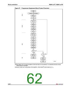
To protect a block follow the flowchart in Figure 27.: Programmer Equipment Block Protect
Flowchart. During the Block Protect algorithm, the A19-A12 Address Inputs indicate the
address of the block to be protected. The block will be correctly protected only if A19-A12
remain valid and stable, and if Chip Enable is kept Low, V , all along the Protect and Verify
IL
phases.
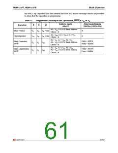
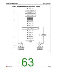
The Chip Unprotect algorithm is used to unprotect all the memory blocks at the same time.
This algorithm can only be used if all of the blocks are protected first. To unprotect the chip
follow Figure 28.: Programmer Equipment Chip Unprotect Flowchart and Table 37.:
Programmer Technique Bus Operations, BYTE = VIH or VIL, which give a summary of each
operation.
The timing on these flowcharts is critical. Care should be taken to ensure that, where a
pause is specified, it is followed as closely as possible. Do not abort the procedure before
reaching the end. Chip Unprotect can take several seconds and a user message should be
provided to show that the operation is progressing.
C.2
In-System Technique
The In-System technique requires a high voltage level on the Reset/Blocks Temporary
Unprotect pin, RP. This can be achieved without violating the maximum ratings of the
components on the microprocessor bus, therefore this technique is suitable for use after the
Flash memory has been fitted to the system.
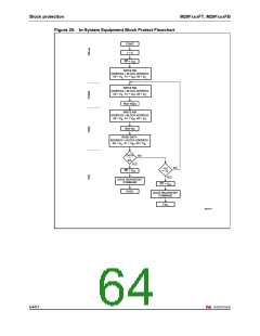
To protect a block follow the flowchart in Figure 29.: In-System Equipment Block Protect
Flowchart. To unprotect the whole chip it is necessary to protect all of the blocks first, then
all the blocks can be unprotected at the same time. To unprotect the chip follow Figure 30.:
In-System Equipment Chip Unprotect Flowchart.
The timing on these flowcharts is critical. Care should be taken to ensure that, where a
pause is specified, it is followed as closely as possible. Do not allow the microprocessor to
service interrupts that will upset the timing and do not abort the procedure before reaching
60/67

 NUMONYX [ NUMONYX B.V ]