Command Interface
M29FxxxFT, M29FxxxFB
within about 100µs, leaving the data unchanged. No error condition is given when protected
blocks are ignored.
During the erase operation the memory will ignore all commands. It is not possible to issue
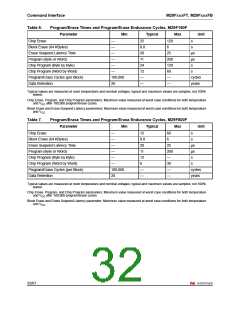
any command to abort the operation. Typical chip erase times are given in Table 6.:
Program/Erase Times and Program/Erase Endurance Cycles, M29F160F. All Bus Read
operations during the Chip Erase operation will output the Status Register on the Data
Inputs/Outputs. See the section on the Status Register for more details.
After the Chip Erase operation has completed the memory will return to the Read Mode,
unless an error has occurred. When an error occurs the memory will continue to output the
Status Register. A Read/Reset command must be issued to reset the error condition and
return to Read Mode.
The Chip Erase Command sets all of the bits in unprotected blocks of the memory to ’1’. All
previous data is lost.
4.8
Block Erase Command
The Block Erase command can be used to erase a list of one or more blocks. Six Bus Write
operations are required to select the first block in the list. Each additional block in the list can
be selected by repeating the sixth Bus Write operation using the address of the additional
block. The Block Erase operation starts the Program/Erase Controller about 50µs after the
last Bus Write operation. Once the Program/Erase Controller starts it is not possible to
select any more blocks. Each additional block must therefore be selected within 50µs of the
last block. The 50µs timer restarts when an additional block is selected. The Status Register
can be read after the sixth Bus Write operation. See the Status Register section for details
on how to identify if the Program/Erase Controller has started the Block Erase operation.
If any selected blocks are protected then these are ignored and all the other selected blocks
are erased. If all of the selected blocks are protected the Block Erase operation appears to
start but will terminate within about 100µs, leaving the data unchanged. No error condition is
given when protected blocks are ignored.
During the Block Erase operation the memory will ignore all commands except the Erase
Suspend command. Typical block erase times are given in Table 6.: Program/Erase Times
and Program/Erase Endurance Cycles, M29F160F. All Bus Read operations during the
Block Erase operation will output the Status Register on the Data Inputs/Outputs. See the
section on the Status Register for more details.
After the Block Erase operation has completed the memory will return to the Read Mode,
unless an error has occurred. When an error occurs the memory will continue to output the
Status Register. A Read/Reset command must be issued to reset the error condition and
return to Read mode.
The Block Erase Command sets all of the bits in the unprotected selected blocks to ’1’. All
previous data in the selected blocks is lost.
4.9
Erase Suspend Command
The Erase Suspend Command may be used to temporarily suspend a Block Erase
operation and return the memory to Read mode. The command requires one Bus Write
operation.
28/67

 NUMONYX [ NUMONYX B.V ]