M29FxxxFT, M29FxxxFB
Bus Operations
3
Bus Operations
There are five standard bus operations that control the device. These are Bus Read, Bus
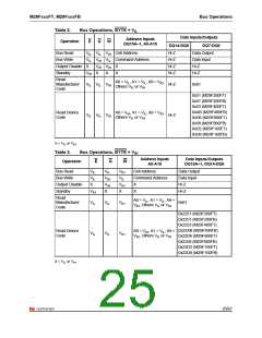
Write, Output Disable, Standby and Automatic Standby. See Table 2.: Bus Operations,
BYTE = VIL and Table 3.: Bus Operations, BYTE = VIH for a summary. Typically glitches of
less than 5ns on Chip Enable or Write Enable are ignored by the memory and do not affect
bus operations.
3.1
3.2
Bus Read
Bus Read operations read from the memory cells, or specific registers in the Command
Interface. A valid Bus Read operation involves setting the desired address on the Address
Inputs, applying a Low signal, V , to Chip Enable and Output Enable and keeping Write
Enable High, V . The Data Inputs/Outputs will output the value, see Figure 20.: Read Mode
AC Waveforms and Table 15.: Read AC Characteristics, for details of when the output
IL
IH
becomes valid.
Bus Write
Bus Write operations write to the Command Interface. A valid Bus Write operation begins by
setting the desired address on the Address Inputs. The Address Inputs are latched by the
Command Interface on the falling edge of Chip Enable or Write Enable, whichever occurs
last. The Data Inputs/Outputs are latched by the Command Interface on the rising edge of
Chip Enable or Write Enable, whichever occurs first. Output Enable must remain High, V ,
IH
during the whole Bus Write operation. See the following figures and tables:
Figure 21.: Write AC Waveforms, Write Enable Controlled
Figure 22.: Write AC Waveforms, Chip Enable Controlled,
Table 16.: Write AC Characteristics, Write Enable Controlled
Table 17.: Write AC Characteristics, Chip Enable Controlled.
3.3
3.4
Output Disable
The Data Inputs/Outputs are in the high impedance state when Output Enable is High, V .
IH
Standby
When Chip Enable is High, V , the memory enters Standby mode and the Data
IH
Inputs/Outputs pins are placed in the high-impedance state. To reduce the Supply Current to
the Standby Supply Current, I
, Chip Enable should be held within V ± 0.2V. For the
CC2
CC
Standby current level see Table 14.: DC Characteristics.
During program or erase operations the memory will continue to use the Program/Erase
Supply Current, I
, for Program or Erase operations until the operation completes.
CC3
23/67

 NUMONYX [ NUMONYX B.V ]