±
15V
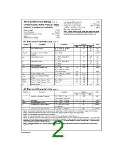
Absolute Maximum Ratings (Note 1)
If Military/Aerospace specified devices are required,
please contact the National Semiconductor Sales Office/
Distributors for availability and specifications.
Input Voltage Range (Note 3)
Output Short Circuit Duration
Storage Temperature Range
Lead Temp. (Soldering, 10 seconds)
ESD rating to be determined.
Continuous
−65˚C to +150˚C
260˚C
±
Supply Voltage
18V
Note 1: “Absolute Maximum Ratings” indicate limits beyond which damage
to the device may occur. Operating Ratings indicate conditions for which the
device is functional, but do not guarantee specific performance limits.
Power Dissipation
Operating Temperature Range
Tj(MAX)
(Note 2)
0˚C to +70˚C
150˚C
±
Differential Input Voltage
30V
DC Electrical Characteristics (Note 5)
Symbol
Parameter
Conditions
TL082C
Typ
Units
Min
Max
15
=
=
VOS
Input Offset Voltage
RS 10 kΩ, TA 25˚C
5
mV
mV
Over Temperature
20
=
∆VOS/∆T
Average TC of Input Offset
Voltage
RS 10 kΩ
10
25
50
µV/˚C
=
IOS
Input Offset Current
Tj 25˚C, (Notes 5, 6)
200
4
pA
nA
Tj ≤ 70˚C
=
IB
Input Bias Current
Tj 25˚C, (Notes 5, 6)
400
8
pA
Tj ≤ 70˚C
nA
=
RIN
Input Resistance
Tj 25˚C
1012
100
Ω
=
=
=
±
±
AVOL
Large Signal Voltage Gain
VS
VO
15V, TA 25˚C
25
15
V/mV
=
10V, RL 2 kΩ
Over Temperature
V/mV
V
=
=
=
±
±
±
±
±
13.5
VO
Output Voltage Swing
Input Common-Mode Voltage
Range
VS
VS
15V, RL 10 kΩ
12
11
VCM
15V
+15
−12
100
100
3.6
V
V
CMRR
PSRR
IS
Common-Mode Rejection Ratio
Supply Voltage Rejection Ratio
Supply Current
RS ≤ 10 kΩ
70
dB
dB
mA
(Note 7)
70
5.6
AC Electrical Characteristics (Note 5)
Symbol
Parameter
Conditions
TL082C
Typ
Units
Min
Max
=
=
Amplifier to Amplifier Coupling
TA 25˚C, f 1Hz-
−120
dB
20 kHz (Input Referred)
=
=
=
=
±
±
SR
Slew Rate
VS
VS
15V, TA 25˚C
8
13
4
V/µs
MHz
=
GBW
en
Gain Bandwidth Product
Equivalent Input Noise Voltage
15V, TA 25˚C
=
√
nV/ Hz
TA 25˚C, RS 100Ω,
25
=
f
1000 Hz
=
=
√
pA/ Hz
in
Equivalent Input Noise Current
Tj 25˚C, f 1000 Hz
0.01
Note 2: For operating at elevated temperature, the device must be derated based on a thermal resistance of 115˚C/W junction to ambient for the N package.
Note 3: Unless otherwise specified the absolute maximum negative input voltage is equal to the negative power supply voltage.
Note 4: The power dissipation limit, however, cannot be exceeded.
=
=
0.
±
Note 5: These specifications apply for V
15V and 0˚C ≤T ≤ +70˚C. V , I and I
OS OS
are measured at V
CM
S
A
B
Note 6: The input bias currents are junction leakage currents which approximately double for every 10˚C increase in the junction temperature, T . Due to the limited
j
production test time, the input bias currents measured are correlated to junction temperature. In normal operation the junction temperature rises above the ambient
=
temperature as a result of internal power dissipation, P . T
D
T
+ θ
P where θ is the thermal resistance from junction to ambient. Use of a heat sink is recom-
D jA
j
A
jA
mended if input bias current is to be kept to a minimum.
Note 7: Supply voltage rejection ratio is measured for both supply magnitudes increasing or decreasing simultaneously in accordance with common practice.
=
±
±
6V to 15V.
V
S
www.national.com
2

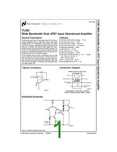
 NSC [ National Semiconductor ]