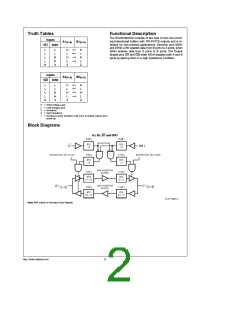
Truth Tables
Functional Description
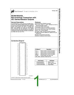
The SCAN182245A consists of two sets of nine non-invert-
ing bidirectional buffers with TRI-STATE outputs and is in-
tended for bus-oriented applications. Direction pins (DIR1
and DIR2) LOW enables data from B ports to A ports, when
HIGH enables data from A ports to B ports. The Output
Enable pins (G1 and G2) when HIGH disables both A and B
ports by placing them in a high impedance condition.
Inputs
A1
(0–8)
B1
(0–8)
²
G1
DIR1
L
L
L
L
H
L
L
H
L
w
w
H
L
H
H
X
H
L
x
H
L
x
Z
Z
Inputs
A2
(0–8)
B2
(0–8)
²
G2
DIR2
L
L
L
L
H
L
L
H
L
w
w
H
L
H
H
X
H
L
x
H
L
x
Z
Z
e
e
e
e
e
H
L
X
Z
²
HIGH Voltage Level
LOW Voltage Level
Immaterial
High Impedance
Inactive-to-Active transition must occur to enable outputs upon
power-up.
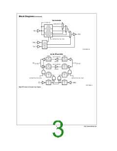
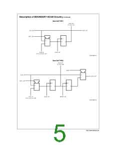
Block Diagrams
A1, B1, G1 and DIR1
TL/F/11657–2
Note: BSR stands for Boundary Scan Register.
http://www.national.com
2

 NSC [ National Semiconductor ]