e
e e
t
f
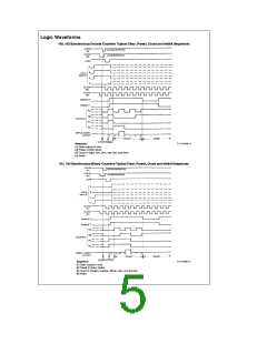
AC Electrical Characteristics (Continued) C 50 pF, t
6 ns (unless otherwise specified)
74HC 54HC
L
r
e
T
25 C
§
A
eb
eb
T
40 to 85 C
T
55 to 125 C
§
§
Guaranteed Limits
Symbol
Parameter
Conditions
V
Units
A
A
CC
Typ
t
t
t
Minimum Hold Time
Enable, Load or Clear
to Clock
2.0V
4.5V
6.0V
0
0
0
0
0
0
0
0
0
ns
ns
ns
H
Minimum Pulse Width
Clock, Clear, or
Load
2.0V
4.5V
6.0V
80
16
14
100
20
17
120
24
20
ns
ns
ns
W
, t
TLH THL
Maximum
Output Rise and
Fall Time
2.0V 40
4.5V
6.0V
75
15
13
95
19
16
110
22
19
ns
ns
ns
8
7
t , t
r f
Maximum Input Rise and
Fall Time
2.0V
4.5V
6.0V
1000
500
400
1000
500
400
1000
500
400
ns
ns
ns
C
C
Power Dissipation
Capacitance (Note 5)
(per package)
90
5
pF
PD
Maximum Input Capacitance
10
10
10
pF
IN
2
V
CC
e
a
I
CC
Note 5:
e
C
determines the no load dynamic power consumption,
P
C
f
V
CC
, and the no load dynamic current consumption,
PD
f
D
PD
a
I
CC
I
C
V
PD CC
.
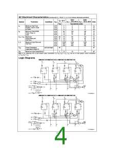
S
Logic Diagrams
MM54HC160/MM74HC160 or MM54HC162/MM74HC162
TL/F/5008–2
MM54HC161/MM74HC161 or MM54HC163/MM74HC163
TL/F/5008–3
4

 NSC [ National Semiconductor ]