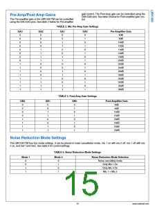
Mute Section
Mic 1 and Mic 2 can be muted independently, using the Mute 1 and Mute 2 pins. See Table 5 for control settings.
TABLE 5. Noise Reduction Mode Settings
Mute 2
Mute 1
Mute Mode Selection
Mic 1 an Mic 2 on
Mic 1 mute
0
0
1
1
0
1
0
1
Mic 2 mute
Mic 1 and Mic 2 mute
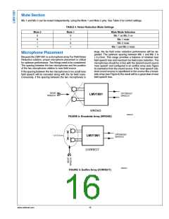
large, the far field noise reduction performance will be de-
graded. The optimum spacing between Mic 1 and Mic 2 is
1.5-2.5cm. This range provides a balance of minimal near
field speech loss and maximum far field noise reduction. The
microphones should be in line with the desired sound source
'near speech' and configured in an endfire array (see Figure
9) orientation from the sound source. If the 'near speech' (de-
sired sound source) is equidistant to the source like a broad-
side array (see Figure 8) the result will be a great deal of near
field speech loss.
Microphone Placement
Because the LMV1091 is a microphone array Far Field Noise
Reduction solution, proper microphone placement is critical
for optimum performance. Two things need to be considered:
The spacing between the two microphones and the position
of the two microphones relative to near field source
If the spacing between the two microphones is too small near
field speech will be canceled along with the far field noise.
Conversely, if the spacing between the two microphones is
30092243
FIGURE 8: Broadside Array (WRONG)
30092242
FIGURE 9: Endfire Array (CORRECT)
www.national.com
16

 NSC [ National Semiconductor ]