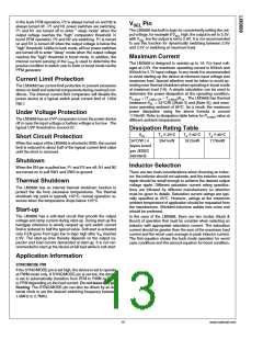
~1.6% of the nominal PWM output voltage (Figure 6). If the
output voltage is below the ‘high’ PFM comparator threshold,
the P1 & P2 (Buck mode) or N2 & P1 (Boost mode) power
switches are turned on. It remains on until the output voltage
reaches the ‘high’ PFM threshold or the peak current exceeds
the IPFM level set for PFM mode. The typical peak current in
PFM mode is: IPFM = 220mA
Internal Synchronous Rectification
While in PWM mode, the LM3668 uses an internal MOSFET
as a synchronous rectifier to reduce rectifier forward voltage
drop and associated power loss. Synchronous rectification
provides a significant improvement in efficiency whenever the
output voltage is relatively low compare to the voltage drop
across an ordinary rectifier diode.
Once the P1 ( Buck mode) or N2 ( Boost mode) power switch
is turned off, the N1 & P2 ( Buck mode) or P1 & P2 (Boost
mode) power switches are turned on until the inductor current
ramps to zero. When the zero inductor current condition is
detected, the N1( Buck mode) or P2 ( Boost mode) power
switches are turned off. If the output voltage is below the ‘high’
PFM comparator threshold, the P1 & P2 (Buck mode) or N2
& P1 ( Boost mode) switches are again turned on and the
cycle is repeated until the output reaches the desired level.
Once the output reaches the ‘high’ PFM threshold, the N1 &
P2 (Buck mode) or P1 & P2 ( Boost mode) switches are turned
on briefly to ramp the inductor current to zero, then both output
switches are turned off and the part enters an extremely low
power mode. Quiescent supply current during this ‘sleep’
mode is 45µA (typ), which allows the part to achieve high ef-
ficiency under extremely light load conditions.
PFM Operation
At very light loads, the converter enters PFM mode and op-
erates with reduced switching frequency and supply current
to maintain high efficiency. The part automatically transitions
into PFM mode when either of two following conditions occur
for a duration of 128 or more clock cycles:
A.ꢁThe inductor current reaches zero.
B.ꢁThe peak inductor current drops below the IMODE level,
(Typically IMODE < 45mA + VIN/80 Ω ).
In PFM operation, the compensation circuit in the error am-
plifier is turned off. The error amplifier works as a hysteretic
comparator. The PFM comparator senses the output voltage
via the feedback pin and controls the switching of the output
FETs such that the output voltage ramps between ~0.8% and
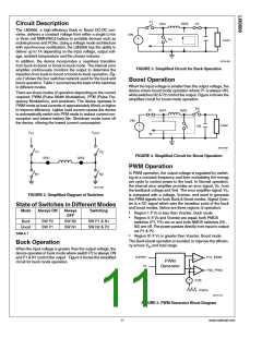
20191413
FIGURE 6. PFM to PWM Mode Transition
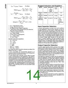
In addition to the auto mode transition, the LM3668 operates
in PFM Buck or PFM Boost based on the following conditions.
There is a small delta (~500mV) known as dv1(~200mV) &
dv2(~300mV) when VOUT_TARGET is very close to VIN where
the LM3668 can be in either Buck or Boost mode. For exam-
ple, when VOUT_TARGET = 3.3V and VIN is between 3.1V &
3.6V, the LM3668 can be in either mode depending on the
VIN vs VOUT_TARGET
.
•
•
•
Region I: If VIN < VOUT_TARGET - dv1, the regulator operates
in Boost mode.
Region II: If VOUT_TARGET - dv1 < VIN < VOUT_TARGET
+
dv2 ,the regulator operates in either Buck or Boost mode.
Region III: If VIN > VOUT_TARGET + dv2, the regulator
operates in Buck mode.
20191414
FIGURE 7. VOUT vs VIN Transition
www.national.com
12

 NSC [ National Semiconductor ]