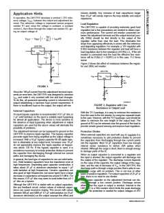
Application Hints (Continued)
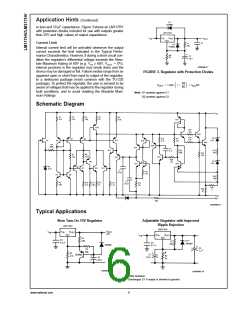
or less and 10 µF capacitance. Figure 3 shows an LM117HV
with protection diodes included for use with outputs greater
than 25V and high values of output capacitance.
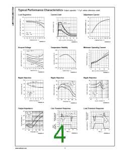
Current Limit
Internal current limit will be activated whenever the output
current exceeds the limit indicated in the Typical Perfor-
mance Characteristics. However, if during a short circuit con-
dition the regulator’s differential voltage exceeds the Abso-
lute Maximum Rating of 60V (e.g. VIN ≥ 60V, VOUT = 0V),
internal junctions in the regulator may break down and the
device may be damaged or fail. Failure modes range from an
apparent open or short from input to output of the regulator,
to a destroyed package (most common with the TO-220
package). To protect the regulator, the user is advised to be
aware of voltages that may be applied to the regulator during
fault conditions, and to avoid violating the Absolute Maxi-
mum Ratings.
DS009062-7
FIGURE 3. Regulator with Protection Diodes
Note: D1 protects against C1
D2 protects against C2
Schematic Diagram
DS009062-8
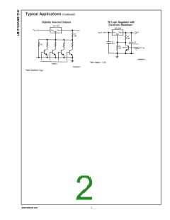
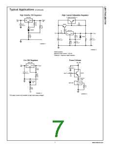
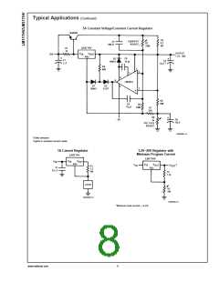
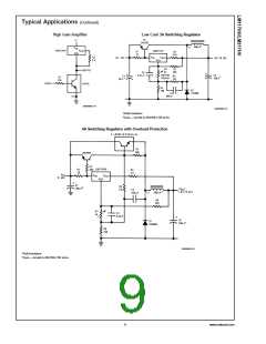
Typical Applications
Slow Turn-On 15V Regulator
Adjustable Regulator with Improved
Ripple Rejection
DS009062-9
DS009062-10
†
Solid tantalum
*Discharges C1 if output is shorted to ground
www.national.com
6

 NSC [ National Semiconductor ]