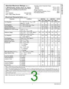
Absolute Maximum Ratings (Note 1)
If Military/Aerospace specified devices are required,
please contact the National Semiconductor Sales Office/
Distributors for availability and specifications.
Operating Junction Temperature Range
LM117HV
−55˚C to +150˚C
0˚C to +125˚C
−65˚C to +150˚C
300˚C
LM317HV
Storage Temperature
(Note 4)
Lead Temperature (Soldering, 10 sec.)
ESD Tolerance (Note 5)
2000V
Power Dissipation
Internally limited
+60V, −0.3V
Input—Output Voltage Differential
Electrical Characteristics (Note 2)
Parameter
Conditions
LM117HV
Typ
LM317HV
Typ
Units
Min
Max Min
Max
Line Regulation
TJ = 25˚C, 3V ≤ VIN − VOUT ≤ 60V
(Note 3) IL = 10 mA
0.01
0.02
0.01
0.04
%/V
%
Load Regulation
TJ = 25˚C, 10 mA ≤ IOUT ≤ IMAX
TJ = 25˚C, 20 ms Pulse
0.1
0.03
50
0.3
0.07
100
5
0.1
0.04
50
0.5
Thermal Regulation
0.07 %/W
Adjustment Pin Current
Adjustment Pin Current Change
100
5
µA
µA
10 mA ≤ IL ≤ IMAX
3.0 V ≤ (VIN − VOUT) ≤ 60V
3.0 V ≤ (VIN − VOUT) ≤ 60V, (Note 4)
10 mA ≤ IOUT ≤ IMAX, P ≤ PMAX
3.0V ≤ (VIN − VOUT) ≤ 60V,
IL = 10 mA, (Note 3)
10 mA ≤ IOUT ≤ IMAX (Note 3)
TMIN ≤ TJ ≤ TMAX
(VIN − VOUT) = 60V
(VIN − VOUT) ≤ 15V
K, T Packages
0.2
0.2
Reference Voltage
Line Regulation
1.20
1.25
0.02
1.30 1.20
1.25
0.02
1.30
0.07
1.5
V
0.05
1
%/V
Load Regulation
0.3
1
0.3
1
%
%
Temperature Stability
Minimum Load Current
Current Limit
3.5
7
3.5
12
mA
1.5
0.5
2.2
0.8
3.5
1.8
1.5
0.5
2.2
0.8
3.7
1.9
A
A
H Package
(VIN − VOUT) ≤ 60V
K, T Packages
0.3
0.03
0.003
65
0.3
0.03
0.003
65
A
H Package
A
RMS Output Noise, % of VOUT
Ripple Rejection Ratio
TJ = 25˚C, 10 Hz ≤ f ≤ 10 kHz
VOUT = 10V, f = 120 Hz
CADJ = 10 µF
%
dB
66
80
66
80
dB
Long-Term Stability
Thermal Resistance,
Junction to Case
TJ = 125˚C
0.3
1
0.3
12
1
15
5
%
H Package
12
15
˚C/W
˚C/W
˚C/W
˚C/W
˚C/W
˚C/W
T Package
4
K Package
2.3
3
2.3
140
50
3
Thermal Resistance,
Junction to Ambient
(no heat sink)
H Package
140
T Package
K Package
35
35
Note 1: “Absolute Maximum Ratings” indicate limits beyond which damage to the device may occur. Operating Ratings indicate conditions for which the device is
functional, but do not guarantee specific performance limits.
Note 2: Unless otherwise specified, these specifications apply: −55˚C ≤ T ≤ +150˚C for the LM117HV, and 0˚C ≤ T ≤ +125˚C for the LM317HV; V − V = 5V
OUT
J
J
IN
and I
= 0.1A for the TO-39 package and I
= 0.5A for the TO-3 and TO-220 packages. Although power dissipation is internally limited, these specifications are
OUT
OUT
applicable for power dissipations of 2W for the TO-39 and 20W for the TO-3 and TO-220. I
is 1.5A for the TO-3 and TO-220 and 0.5A for the TO-39 package.
MAX
Note 3: Regulation is measured at constant junction temperature. Changes in output voltage due to heating effects must be taken into account separately. Pulse test-
ing with low duty cycle is used.
Note 4: Refer to RETS117HVH for LM117HVH or RETS117HVK for LM117HVK military specificatioins.
Note 5: Human body model, 1.5 kΩ in series with 100 pF.
3
www.national.com

 NSC [ National Semiconductor ]