Application Information (Continued)
teristic may cause instability or EMI problems. Ultra-fast
recovery diodes typically have reverse recovery times of 50
ns or less. Rectifiers such as the 1N5400 series are much
too slow and should not be used.
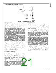
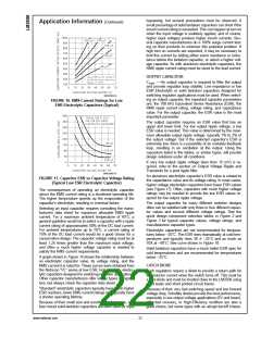
DS012593-35
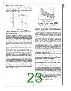
FIGURE 19. (∆IIND) Peak-to-Peak Inductor
Ripple Current (as a Percentage of the
Load Current) vs Load Current
By allowing the percentage of inductor ripple current to
increase for low load currents, the inductor value and size
can be kept relatively low.
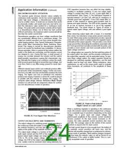
DS012593-34
FIGURE 18. Capacitor ESR Change vs Temperature
When operating in the continuous mode, the inductor current
waveform ranges from a triangular to a sawtooth type of
waveform (depending on the input voltage), with the average
value of this current waveform equal to the DC output load
current.
INDUCTOR SELECTION
All switching regulators have two basic modes of operation;
continuous and discontinuous. The difference between the
two types relates to the inductor current, whether it is flowing
continuously, or if it drops to zero for a period of time in the
normal switching cycle. Each mode has distinctively different
operating characteristics, which can affect the regulators
performance and requirements. Most switcher designs will
operate in the discontinuous mode when the load current is
low.
Inductors are available in different styles such as pot core,
toroid, E-core, bobbin core, etc., as well as different core
materials, such as ferrites and powdered iron. The least
expensive, the bobbin, rod or stick core, consists of wire
wound on a ferrite bobbin. This type of construction makes
for an inexpensive inductor, but since the magnetic flux is not
completely contained within the core, it generates more
Electro-Magnetic Interference (EMl). This magnetic flux can
induce voltages into nearby printed circuit traces, thus caus-
ing problems with both the switching regulator operation and
nearby sensitive circuitry, and can give incorrect scope read-
ings because of induced voltages in the scope probe. Also
see section on Open Core Inductors.
The LM2598 (or any of the Simple Switcher family) can be
used for both continuous or discontinuous modes of opera-
tion.
In many cases the preferred mode of operation is the con-
tinuous mode. It offers greater output power, lower peak
switch, inductor and diode currents, and can have lower
output ripple voltage. But it does require larger inductor
values to keep the inductor current flowing continuously,
especially at low output load currents and/or high input volt-
ages.
When multiple switching regulators are located on the same
PC board, open core magnetics can cause interference
between two or more of the regulator circuits, especially at
high currents. A torroid or E-core inductor (closed magnetic
structure) should be used in these situations.
To simplify the inductor selection process, an inductor selec-
tion guide (nomograph) was designed (see Figure 3 through
Figure 6). This guide assumes that the regulator is operating
in the continuous mode, and selects an inductor that will
allow a peak-to-peak inductor ripple current to be a certain
percentage of the maximum design load current. This
peak-to-peak inductor ripple current percentage is not fixed,
but is allowed to change as different design load currents are
selected. (See Figure 19.)
The inductors listed in the selection chart include ferrite
E-core construction for Schott, ferrite bobbin core for Renco
and Coilcraft, and powdered iron toroid for Pulse Engineer-
ing.
Exceeding an inductor’s maximum current rating may cause
the inductor to overheat because of the copper wire losses,
or the core may saturate. If the inductor begins to saturate,
the inductance decreases rapidly and the inductor begins to
look mainly resistive (the DC resistance of the winding). This
can cause the switch current to rise very rapidly and force
the switch into a cycle-by-cycle current limit, thus reducing
the DC output load current. This can also result in overheat-
ing of the inductor and/or the LM2598. Different inductor
types have different saturation characteristics, and this
should be kept in mind when selecting an inductor.
The inductor manufacturer’s data sheets include current and
energy limits to avoid inductor saturation.
23
www.national.com

 NSC [ National Semiconductor ]