Application Information (Continued)
DS012593-65
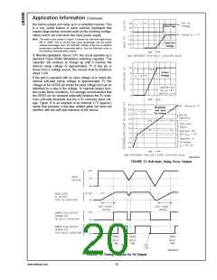
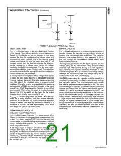
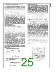
FIGURE 15. External 3.7V Soft-Start Clamp
DELAY CAPACITOR
INPUT CAPACITOR
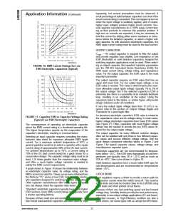
CDELAY —Provides delay for the error flag output. See the
upper curve in Figure 13, and also refer to timing diagrams in
Figure 14. A capacitor on this pin provides a time delay
between the time the regulated output voltage (when it is
increasing in value) reaches 95% of the nominal output
voltage, and the time the error flag output goes high. A 3 µA
constant current from the delay pin charges the delay ca-
pacitor resulting in a voltage ramp. When this voltage
reaches a threshold of approximately 1.3V, the open collec-
tor error flag output (or power OK) goes high. This signal can
be used to indicate that the regulated output has reached the
correct voltage and has stabilized.
CIN —A low ESR aluminum or tantalum bypass capacitor is
needed between the input pin and ground pin. It must be
located near the regulator using short leads. This capacitor
prevents large voltage transients from appearing at the in-
put, and provides the instantaneous current needed each
time the switch turns on.
The important parameters for the Input capacitor are the
voltage rating and the RMS current rating. Because of the
relatively high RMS currents flowing in a buck regulator’s
input capacitor, this capacitor should be chosen for its RMS
current rating rather than its capacitance or voltage ratings,
although the capacitance value and voltage rating are di-
rectly related to the RMS current rating.
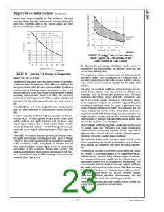
If, for any reason, the regulated output voltage drops by 5%
or more, the error output flag (Pin 3) immediately goes low
(internal transistor turns on). The delay capacitor provides
very little delay if the regulated output is dropping out of
regulation. The delay time for an output that is decreasing is
approximately a 1000 times less than the delay for the rising
output. For a 0.1 µF delay capacitor, the delay time would be
approximately 50 ms when the output is rising and passes
through the 95% threshold, but the delay for the output
dropping would only be approximately 50 µs.
The RMS current rating of a capacitor could be viewed as a
capacitor’s power rating. The RMS current flowing through
the capacitors internal ESR produces power which causes
the internal temperature of the capacitor to rise. The RMS
current rating of a capacitor is determined by the amount of
current required to raise the internal temperature approxi-
mately 10˚C above an ambient temperature of 105˚C. The
ability of the capacitor to dissipate this heat to the surround-
ing air will determine the amount of current the capacitor can
safely sustain. Capacitors that are physically large and have
a large surface area will typically have higher RMS current
ratings. For a given capacitor value, a higher voltage elec-
trolytic capacitor will be physically larger than a lower voltage
capacitor, and thus be able to dissipate more heat to the
surrounding air, and therefore will have a higher RMS cur-
rent rating.
RPull Up —The error flag output, (or power OK) is the col-
lector of
a NPN transistor, with the emitter internally
grounded. To use the error flag, a pullup resistor to a positive
voltage is needed. The error flag transistor is rated up to a
maximum of 45V and can sink approximately 3 mA. If the
error flag is not used, it can be left open.
FEEDFORWARD CAPACITOR
(Adjustable Output Voltage Version)
CFF — A Feedforward Capacitor CFF, shown across R2 in
Figure 1 is used when the output voltage is greater than 10V
or then COUT has a very low ESR. This capacitor adds lead
compensation to the feedback loop and increases the phase
margin for better loop stability. For CFF selection, see the
design procedure section.
>
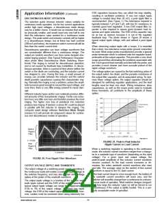
If the output ripple is large ( 5% of the nominal output
voltage), this ripple can be coupled to the feedback pin
through the feedforward capacitor and cause the error com-
parator to trigger the error flag. In this situation, adding a
resistor, RFF, in series with the feedforward capacitor, ap-
proximately 3 times R1, will attenuate the ripple voltage at
the feedback pin.
21
www.national.com

 NSC [ National Semiconductor ]