LM2587-ADJ
Electrical Characteristics (Continued)
Symbol
Parameters
Conditions
Typical
1.230
1.5
Min
Max
Units
V
UNIQUE DEVICE PARAMETERS (Note 5)
VREF
∆VREF
GM
Output Reference
Voltage
Measured at Feedback Pin
1.208/1.205
1.252/1.255
=
VCOMP 1.0V
=
Reference Voltage
Line Regulation
Error Amp
VIN 4V to 40V
mV
=
ICOMP −30 µA to +30 µA
3.200
670
1.800
6.000
mmho
V/V
nA
=
VCOMP 1.0V
Transconductance
Error Amp
=
AVOL
VCOMP 0.5V to 1.6V
400/200
=
RCOMP 1.0 MΩ (Note 6)
Voltage Gain
Error Amp
=
IB
VCOMP 1.0V
125
425/600
Input Bias Current
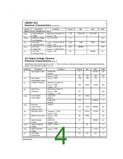
All Output Voltage Versions
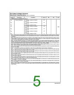
Electrical Characteristics (Note 5)
=
Specifications with standard type face are for TJ 25˚C, and those in bold type face apply over full Operating Temperature
=
Range. Unless otherwise specified, VIN 5V.
Symbol
Parameters
Conditions
Typical
Min
Max
Units
IS
Input Supply Current
(Switch Off)
(Note 8)
11
15.5/16.5
mA
=
ISWITCH 3.0A
85
140
165
mA
V
=
VUV
Input Supply
RLOAD 100Ω
3.30
3.05
3.75
Undervoltage Lockout
Oscillator Frequency
fO
Measured at Switch Pin
=
RLOAD 100Ω
100
85/75
115/125
kHz
=
VCOMP 1.0V
fSC
Short-Circuit
Frequency
Measured at Switch Pin
=
RLOAD 100Ω
25
2.8
kHz
V
=
VFEEDBACK 1.15V
VEAO
Error Amplifier
Output Swing
Upper Limit
(Note 7)
2.6/2.4
Lower Limit
(Note 8)
0.25
0.40/0.55
V
IEAO
Error Amp
(Note 9)
Output Current
(Source or Sink)
Soft Start Current
165
11.0
98
110/70
8.0/7.0
93/90
260/320
µA
µA
%
µA
V
=
ISS
VFEEDBACK 0.92V
17.0/19.0
=
VCOMP 1.0V
=
D
Maximum Duty Cycle
RLOAD 100Ω
(Note 7)
IL
Switch Leakage
Current
Switch Off
15
300/600
=
VSWITCH 60V
=
VSUS
VSAT
ICL
Switch Sustaining
Voltage
dV/dT 1.5V/ns
65
=
Switch Saturation
Voltage
ISWITCH 5.0A
0.7
6.5
1.1/1.4
V
NPN Switch
Current Limit
5.0
9.5
A
www.national.com
4

 NSC [ National Semiconductor ]