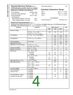
Electrical Characteristics (Note 3)
Specifications with standard type face are for TJ = 25˚C, and those with boldface type apply over full Operating Tempera-
ture Range. Unless otherwise specified, VIN − VOUT = 5V, and IOUT = 10 mA.
Parameter
Conditions
LM317A
Typ
LM317
Typ
Units
Min
Max
Min
Max
1.30
Reference Voltage
1.238 1.250 1.262
V
V
3V ≤ (VIN − VOUT) ≤ 40V,
1.225 1.250 1.270
1.20
1.25
10 mA ≤ IOUT ≤ IMAX, P ≤ PMAX
3V ≤ (VIN − VOUT) ≤ 40V (Note 4)
Line Regulation
Load Regulation
0.005
0.01
0.1
0.01
0.02
0.5
1
0.01
0.02
0.1
0.04
0.07
0.5
%/V
%/V
%
10 mA ≤ IOUT ≤ IMAX (Note 4)
0.3
0.3
1.5
%
Thermal Regulation
Adjustment Pin Current
Adjustment Pin Current
Change
20 ms Pulse
0.04
50
0.07
100
5
0.04
50
0.07
100
5
%/W
µA
10 mA ≤ IOUT ≤ IMAX
3V ≤ (VIN − VOUT) ≤ 40V
TMIN ≤ TJ ≤ TMAX
(VIN − VOUT) = 40V
(VIN − VOUT) ≤ 15V
K, T, S Packages
H Package
0.2
0.2
µA
Temperature Stability
Minimum Load Current
Current Limit
1
1
%
3.5
10
3.5
10
mA
1.5
0.5
1.5
2.2
0.8
2.2
3.4
1.8
3.4
1.5
0.5
1.5
2.2
0.8
2.2
3.4
1.8
3.4
A
A
A
MP Package
(VIN − VOUT) = 40V
K, T, S Packages
H Package
0.15
0.075
0.15
0.4
0.2
0.15
0.075
0.15
0.4
0.2
A
A
MP Package
0.4
0.4
A
RMS Output Noise, % of VOUT
Ripple Rejection Ratio
10 Hz ≤ f ≤ 10 kHz
VOUT = 10V, f = 120 Hz,
CADJ = 0 µF
0.003
65
0.003
65
%
dB
VOUT = 10V, f = 120 Hz,
CADJ = 10 µF
66
80
66
80
dB
Long-Term Stability
Thermal Resistance,
Junction-to-Case
TJ = 125˚C, 1000 hrs
K Package
0.3
1
0.3
2.3
5
1
3
%
˚C/W
˚C/W
˚C/W
˚C/W
˚C/W
˚C/W
˚C/W
˚C/W
˚C/W
˚C/W
MDT Package
H Package
12
4
15
5
12
4
15
T Package
MP Package
23.5
35
23.5
35
92
140
50
50
Thermal Resistance,
Junction-to-Ambient (No Heat
Sink)
K Package
MDT Package(Note 6)
H Package
140
50
T Package
S Package (Note 6)
50
Note 1: Absolute Maximum Ratings indicate limits beyond which damage to the device may occur. Operating Ratings indicate conditions for which the device is
intended to be functional, but do not guarantee specific performance limits. For guaranteed specifications and test conditions, see the Electrical Characteristics. The
guaranteed specifications apply only for the test conditions listed.
Note 2: Refer to RETS117H drawing for the LM117H, or the RETS117K for the LM117K military specifications.
Note 3: Although power dissipation is internally limited, these specifications are applicable for maximum power dissipations of 2W for the TO-39 and SOT-223 and
20W for the TO-3, TO-220, and TO-263. I
is 1.5A for the TO-3, TO-220, and TO-263 packages, 0.5A for the TO-39 package and 1A for the SOT-223 Package.
MAX
All limits (i.e., the numbers in the Min. and Max. columns) are guaranteed to National’s AOQL (Average Outgoing Quality Level).
Note 4: Regulation is measured at a constant junction temperature, using pulse testing with a low duty cycle. Changes in output voltage due to heating effects are
covered under the specifications for thermal regulation.
Note 5: Human body model, 100 pF discharged through a 1.5 kΩ resistor.
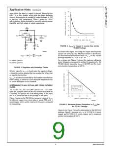
Note 6: If the TO-263 or TO-252 packages are used, the thermal resistance can be reduced by increasing the PC board copper area thermally connected to the
package. Using 0.5 square inches of copper area. θ is 50˚C/W; with 1 square inch of copper area, θ is 37˚C/W; and with 1.6 or more square inches of copper
JA
JA
area, θ is 32˚C/W. If the SOT-223 package is used, the thermal resistance can be reduced by increasing the PC board copper area (see applications hints for
JA
heatsinking).
5
www.national.com

 NSC [ National Semiconductor ]