ESD rating is to be determined.
Absolute Maximum Ratings (Notes 1, 8)
If Military/Aerospace specified devices are required,
please contact the National Semiconductor Sales Office/
Distributors for availability and specifications.
Maximum Junction Temperature
LM10
150˚C
100˚C
85˚C
LM10B
LM10C
LM10/LM10B/ LM10BL/
LM10C
LM10CL
Total Supply Voltage
45V
7V
Operating Ratings
Package Thermal Resistance
±
±
7V
Differential Input Voltage (Note 2)
Power Dissipation (Note 3)
Output Short-circuit Duration (Note 4)
Storage-Temp. Range
40V
internally limited
continuous
θJA
−55˚C to +150˚C
H Package
N Package
WM Package
θJC
150˚C/W
87˚C/W
90˚C/W
Lead Temp. (Soldering, 10 seconds)
Metal Can
300˚C
260˚C
215˚C
220˚C
Lead Temp. (Soldering, 10 seconds) DIP
Vapor Phase (60 seconds)
Infrared (15 seconds)
H Package
45˚C/W
See AN-450 “Surface Mounting Methods and Their Effect on
Product Reliability” for other methods of soldering surface
mount devices.
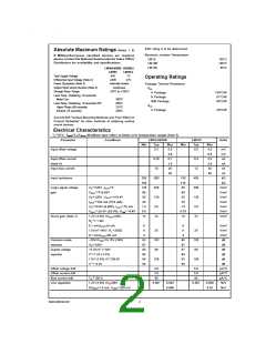
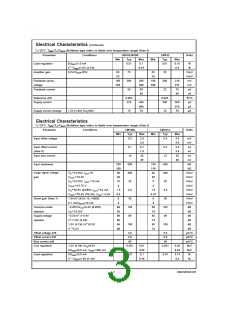
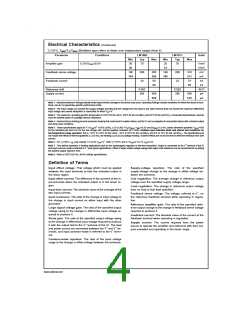
Electrical Characteristics
=
TJ 25˚C, TMIN≤TJ≤TMAX (Boldface type refers to limits over temperature range) (Note 5)
Parameter
Conditions
LM10/LM10B
LM10C
Typ
Units
Min
Typ
Max
2.0
3.0
0.7
1.5
20
Min
Max
4.0
5.0
2.0
3.0
30
Input offset voltage
0.3
0.5
mV
mV
Input offset current
(Note 6)
0.25
10
0.4
12
nA
nA
Input bias current
nA
30
40
nA
Input resistance
250
150
120
80
500
400
130
3.0
33
150
115
80
400
400
130
3.0
33
kΩ
kΩ
=
=
±
Large signal voltage
gain
VS 20V, IOUT
0
V/mV
V/mV
V/mV
V/mV
V/mV
V/mV
V/mV
=
±
VOUT 19.95V
50
=
=
±
±
VS 20V, VOUT 19.4V
50
25
=
±
±
IOUT 20 mA ( 15 mA)
20
15
=
=
±
±
VS 0.6V (0.65V), IOUT 2 mA
1.5
0.5
14
1.0
0.75
10
=
=
±
±
VOUT 0.4V ( 0.3V), VCM −0.4V
Shunt gain (Note 7)
1.2V (1.3V) ≤VOUT≤40V,
=
RL 1.1 kΩ
0.1 mA≤IOUT≤5 mA
6
6
V/mV
V/mV
V/mV
dB
1.5V≤V+≤40V, RL 250Ω
8
25
102
96
6
25
102
96
=
0.1 mA≤IOUT≤20 mA
4
4
Common-mode
rejection
−20V≤VCM≤19.15V (19V)
93
87
90
84
96
90
90
87
87
84
93
90
=
±
VS 20V
dB
Supply-voltage
rejection
−0.2V≥V−≥−39V
dB
V+ 1.0V (1.1V)
dB
=
1.0V (1.1V) ≤V+≤39.8V
106
106
dB
V− −0.2V
dB
=
Offset voltage drift
Offset current drift
Bias current drift
Line regulation
2.0
2.0
60
5.0
5.0
µV/˚C
pA/˚C
pA/˚C
%/V
%/V
<
TC 100˚C
90
1.2V (1.3V) ≤VS≤40V
0.001
0.003
0.001
0.008
=
0≤IREF≤1.0 mA, VREF 200 mV
0.006
0.01
www.national.com
2

 NSC [ National Semiconductor ]