Integrated Functions (Continued)
4.5.3 Hardware Cursor
4.5.4 Display Timing Generator
The display controller contains hardware cursor logic to
allow overlay of the cursor image onto the pixel data
stream. Overhead for updating this image on the screen is
kept to a minimum by requiring that only the X and Y posi-
tion be changed. This eliminates "submarining" effects
commonly associated with software cursors. The cursor,
32x32 pixels with 2-bpp, is loaded into off-screen memory
The display controller features a fully programmable tim-
ing generator for generating all timing control signals for
the display. The timing control signals include horizontal
and vertical sync and blank signals in addition to timing for
active and overscan regions of the display. The timing
generator is similar in function to the CRTC of the original
VGA, although programming is more straightforward. Pro-
gramming of the timing registers are supported by
National via a BIOS INT10 call during a mode set. When
programming the timing registers directly, extreme care
should be taken to ensure that all timing is compatible with
the display device.
within
the
graphics
memory
aperture.
The
DC_CUR_ST_OFFSET programs the cursor start (see
Table 4-30 on page 148). The 2-bit code selects color 0,
color 1, transparent, or background-color inversion for
each pixel in the cursor. The two cursor colors will be
stored as extensions to the normal 256-entry palette at
locations 100h and 101h.
The timing generator supports overscan to maintain full
backward compatibility with the VGA standard. This fea-
ture is supported primarily for CRT display devices since
flat panel displays have fixed resolutions and do not pro-
vide for overscan. When a display mode is selected hav-
ing a lower resolution than the panel resolution, the GXLV
processor supports a mechanism to center the display by
stretching the border to fill the remainder of the screen.
The border color is at palette extension 104h.
The 2-bit cursor codes are as follows:
AND
XOR
Displayed
0
0
1
1
0
1
0
1
Cursor Color 0
Cursor Color 1
Transparent − Background Pixel
Inverted − Bit-wise Inversion of Back-
ground Pixel
4.5.5 Dither and Frame Rate Modulation
The cursor overlay patterns are loaded to independent
memory locations, usually mapped above the frame buffer
and compressed display buffer (off-screen). The cursor
buffer must start on a DWORD boundary. It is linearly
mapped, and is always 256 bytes in size. If there is
enough room (256 bytes) after the compression-buffer line
but before the next frame-buffer line starts, the cursor pat-
tern may be loaded into this area to make efficient use of
the graphics memory.
The display controller supports 2x2 dither and two-level
frame rate modulation (FRM) to increase the apparent
number of colors displayed on 9-bit or 12-bit TFT panels.
Dither and FRM are individually programmable. With dith-
ering and FRM enabled, 185,193 colors are possible on a
9-bit TFT panel, and 226,981 colors are possible on a 12-
bit TFT panel.
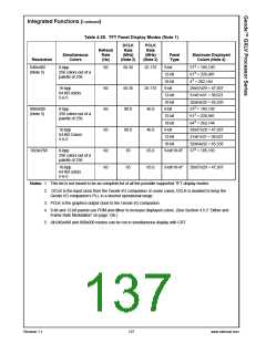
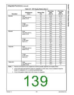
4.5.6 Display Modes
The GXLV processor’s display controller is programmable
and supports resolutions up to 1024x768 at 16 bits per
pixel and resolutions up to 1280x1024 at 8 bits per pixel.
This means the GXLV processor supports the standard
display resolutions of 640x480, 800x600, and 1024x768
display resolutions at both 8 and 16 bits per pixel and
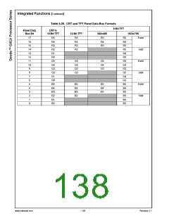
1280x1024 resolution at 8 bits per pixel only. Two 16-bit
display formats are supported: RGB 5-6-5 and RGB 5-5-
5. Table 4-26 lists how the RGB data is mapped onto the
pixel data bus for the CRT and various TFT interfaces. All
CRT modes can have VESA-compatible timing. Table 4-
25 lists some of the supported TFT panel display modes
and Table 4-27 lists some of the supported CRT display
modes.
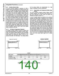
Each pattern is a 32x32-pixel array of 2-bit codes. The
codes are a combination of AND mask and XOR mask for
a particular pixel. Each line of an overlay pattern is stored
as two DWORDs, with each DWORD containing the AND
masks for 16 pixels in the upper word and the XOR masks
for 16 pixels in the lower word. DWORDs are arranged
with the leftmost pixel block being least significant and the
rightmost pixel block being most significant. Pixels within
words are arranged with the leftmost pixels being most
significant and the rightmost pixels being least significant.
Multiple cursor patterns may be loaded into the off-screen
memory. An application may simply change the cursor
start offset to select a new cursor pattern. The new cursor
pattern will become effective at the start of the next frame
scan.
www.national.com
136
Revision 1.1

 NSC [ National Semiconductor ]