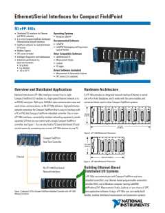
Ethernet/Serial Interfaces for Compact FieldPoint
Shock and Vibration
Operating vibration
Random (IEC 60068-2-64)............... 10 to 500 Hz, 5 grms
Sinusoidal (IEC 60068-2-6) ............. 10 to 500 Hz, 5 g
Operating shock
Specifications
Network
Network interface............................... 10BaseT and 100BaseTX Ethernet
Compatibility....................................... IEEE802.3
(IEC 60068-2-27) ............................. 50 g, 3 ms half sine, 18 shocks at
6 orientations; 30 g, 11 ms half
Communication rates.......................... 10 or 100 Mb/s, autonegotiated
Maximum cabling distance................. 100 m/segment
Maximum power to I/O modules........ 9 W
sine, 18 shocks at 6 orientations
Maximum number of banks................ Determined by network topology
Safety
Serial Port
One RS232 (DCE) serial port
Baud rate ........................................ 300 to 115,200 b/s
This product is designed to meet the requirements of the following
standards of safety for electrical equipment for measurement, control,
and laboratory use:
Data bits .........................................
Stop bits..........................................
Parity............................................... None
Flow control.................................... None
8
1
• IEC 61010-1, EN 61010-1
• UL 61010-1
• CAN/CSA-C22.2 No. 61010-1
Note: For UL, hazardous location, and other safety certifications, refer to the product label or
visit ni.com/certification, search by model number or product line, and click the appropriate
link in the Certification column.
Power Requirement
Power supply range ............................ 11 to 30 VDC
Recommended power supply.............. 20 W
Power consumption ............................ 6.1 W + 1.1 (I/O module)
Electromagnetic Compatibility
Emissions ............................................ EN 55011 Class A at 10 m
FCC Part 15A above 1 GHz
Immunity.............................................. EN 61326:1997 + A2:2002, Table 1
CE, C-Tick, and FCC Part 15
Safety Isolation Voltage
Isolation voltage is verified by a dielectric withstand test between
module and backplane.
(Class A) Compliant
Continuous .......................................... 250 Vrms
,
Note: For EMC compliance, operate this device with shielded cabling.
Measurement Category II
Withstand............................................ 2,300 Vrms, 5 s max
CE Compliance
This product meets the essential requirements of applicable European
directives, as amended for CE marking, as follows:
Physical Characteristics
Screw-terminal wiring ........................ 14 to 22 AWG copper wire with
7 mm (0.28 in.) of insulation
Low-voltage directive (safety) ............ 73/23/EEC
Electromagnetic compatibility
directive (EMC).................................... 89/336/EEC
Note: Refer to the Declaration of Conformity (DoC) for this product for any additional regulatory
compliance information. To obtain the DoC for this product, visit ni.com/certification, search
by model number or product line, and click the appropriate link in the Certification column.
stripped from the end
Torque for screw terminals................. 0.5 to 0.6 N • m
(4.4 to 5.3 lb • in.)
Weight
cFP-1804 ......................................... 935 g (2 lb 1 oz)
cFP-1808 ......................................... 1,595 g (3 lb 8 oz)
Environmental
FieldPoint modules are intended for indoor use only. For outdoor use,
they must be installed in a suitable sealed enclosure.
Operating temperature ....................... -40 to 70 °C
Storage temperature........................... -55 to 85 °C
Relative humidity ................................ 10 to 90%, noncondensing
Maximum altitude............................... 2,000 m; at higher altitudes
the isolation voltage ratings
must be lowered
Pollution Degree .................................
2
BUY ONLINE at ni.com or CALL (800) 813 3693 (U.S.)
4

 NI [ National Instruments ]