74VHC541; 74VHCT541
Nexperia
Octal buffer/line driver; 3-state
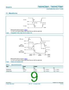
t
W
V
I
90 %
negative
pulse
V
V
V
M
M
10 %
0 V
t
t
r
f
t
t
f
r
V
I
90 %
positive
pulse
V
M
M
10 %
0 V
t
W
V
CC
V
CC
V
V
O
I
R
L
S1
G
open
DUT
R
T
C
L
001aad983
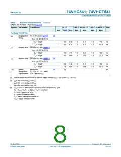
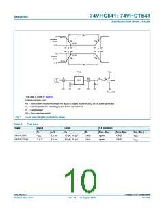
Test data is given in Table 9.
Definitions test circuit:
RT = Termination resistance should be equal to output impedance Zo of the pulse generator
CL = Load capacitance including jig and probe capacitance
RL = Load resistor
S1 = Test selection switch
Fig 7. Load circuitry for switching times
Table 9.
Type
Test data
Input
Load
S1 position
tPHL, tPLH
open
VI
tr, tf
CL
RL
tPZH, tPHZ
GND
tPZL, tPLZ
VCC
74VHC541
VCC
3.0 V
3.0 ns
3.0 ns
15 pF, 50 pF
15 pF, 50 pF
1 kΩ
1 kΩ
74VHCT541
open
GND
VCC
©
74VHC_VHCT541_1
Nexperia B.V. 2017. All rights reserved
Product data sheet
Rev. 01 — 12 August 2009
10 of 16

 NEXPERIA [ Nexperia ]