Nexperia
74HC253; 74HCT253
Dual 4-input multiplexer; 3-state
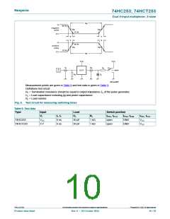
11.1. Waveforms and test circuit
V
I
V
V
M
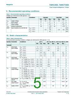
Sn, 1In, 2ln input
GND
M
t
t
PHL
PLH
V
OH
90 %
V
V
M
nY output
M
10 %
V
OL
t
t
THL
TLH
001aal855
Measurement points are given in Table 8.
VOL and VOH are typical voltage output levels that occur with the output load.
Fig. 4. Propagation delays input (Sn, 1In, 2In) to output (nY) and output (nY) transition times
t
t
f
r
V
I
90 %
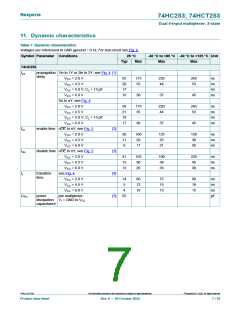
nOE input
V
M
10 %
GND
t
t
PLZ
PZL
V
CC
output
V
LOW-to-OFF
OFF-to-LOW
M
10 %
V
OL
t
t
PHZ
PZH
V
OH
90 %
output
HIGH-to-OFF
OFF-to-HIGH
V
M
GND
outputs
enabled
outputs
disabled
outputs
enabled
001aal856
Measurement points are given in Table 8.
VOL and VOH are typical voltage output levels that occur with the output load.
Fig. 5. 3-state output enable and disable times
Table 8. Measurement points
Type
Input
VM
Output
VM
74HC253
0.5 × VCC
1.3 V
0.5 × VCC
1.3 V
74HCT253
©
74HC_HCT253
All information provided in this document is subject to legal disclaimers.
Nexperia B.V. 2022. All rights reserved
Product data sheet
Rev. 9 — 20 October 2022
9 / 16

 NEXPERIA [ Nexperia ]