Nexperia
74HC253; 74HCT253
Dual 4-input multiplexer; 3-state
Symbol Parameter Conditions
74HCT253
25 °C
-40 °C to +85 °C -40 °C to +125 °C Unit
Typ
Max
Max
Max
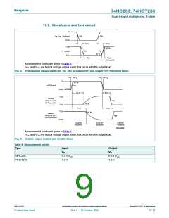
tpd
propagation 1ln to 1Y or 2ln to 2Y; see Fig. 4 [1]
delay
VCC = 4.5 V
20
17
38
-
48
-
57
-
ns
ns
VCC = 5.0 V; CL = 15 pF
Sn to nY; see Fig. 4
VCC = 4.5 V
22
19
14
40
-
50
-
60
-
ns
ns
ns
VCC = 5.0 V; CL = 15 pF
ten
tdis
tt
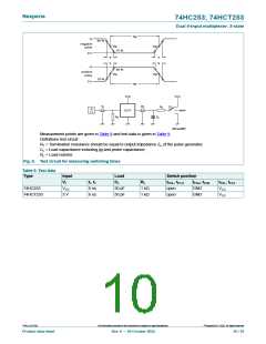
enable time nOE to nY; VCC = 4.5 V;
see Fig. 5
[2]
[3]
30
38
45
disable time nOE to nY; VCC = 4.5 V;
see Fig. 5
13
5
30
12
-
38
15
-
45
18
-
ns
ns
pF
transition
time
VCC = 4.5 V; see Fig. 4
CPD
power
per multiplexer;
[5]
55
dissipation VI = GND to VCC - 1.5 V
capacitance
[1] tpd is the same as tPHL, tPLH
[2] ten is the same as tPZH, tPZL
[3] tdis is the same as tPHZ, tPLZ
[4] tt is the same as tTHL, tTLH
.
.
.
.
[5] CPD is used to determine the dynamic power dissipation (PD in μW).
PD = CPD × VCC 2 × fi × N + ∑(CL × VCC 2 × fo) where:
fi = input frequency in MHz;
fo = output frequency in MHz;
CL = output load capacitance in pF;
VCC = supply voltage in V;
N = number of inputs switching;
∑(CL × VCC 2 × fo) = sum of outputs.
©
74HC_HCT253
All information provided in this document is subject to legal disclaimers.
Nexperia B.V. 2022. All rights reserved
Product data sheet
Rev. 9 — 20 October 2022
8 / 16

 NEXPERIA [ Nexperia ]