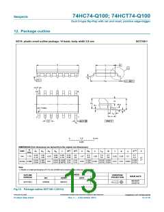
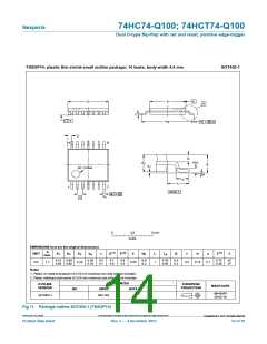
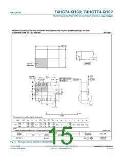
74HC74-Q100; 74HCT74-Q100
Nexperia
Dual D-type flip-flop with set and reset; positive edge-trigger
W
:
9
,
ꢅꢂꢊꢎ
QHJDWLYHꢊ
SXOVH
9
9
9
9
0
0
0
ꢁꢂꢊꢎ
ꢅꢂꢊꢎ
*1'
W
W
U
I
W
W
I
U
9
,
SRVLWLYHꢊ
SXOVH
0
ꢁꢂꢊꢎ
*
*1'
W
:
9
&&
9
,
9
2
'87
5
7
&
/
ꢅꢅꢁDDKꢉꢈꢂꢋ
ꢋ
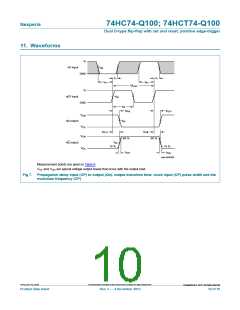
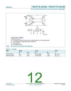
Test data is given in Table 10.
Definitions test circuit:
RT = Termination resistance should be equal to output impedance Zo of the pulse generator.
CL = Load capacitance including jig and probe capacitance.
RL = Load resistance.
S1 = Test selection switch.
Fig 9. Test circuit for measuring switching times
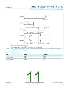
Table 10. Test data
Type
Input
VI
Load
Test
tr, tf
6 ns
6 ns
CL
RL
74HC74-Q100
74HCT74-Q100
VCC
3 V
15 pF, 50 pF
15 pF, 50 pF
1 k
1 k
tPLH, tPHL
tPLH, tPHL
74HC_HCT74_Q100
All information provided in this document is subject to legal disclaimers.
©
Nexperia B.V. 2017. All rights reserved
Product data sheet
Rev. 3 — 4 December 2015
12 of 19

 NEXPERIA [ Nexperia ]