CHAPTER 1 INTRODUCTION
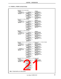
{ Serial interface Asynchronous serial interface (UART):
3-wire serial I/O (CSI0):
2 channels
2 channels
3-wire serial I/O (with automatic transmit/receive function) (CSIA): 2 channels
I2C bus interface (I2C):
1 channel
(µPD703212Y, 703213Y, 703214Y, 703215Y, 70F3214Y, 70F3214HY, 70F3215HY)
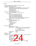
{ A/D converter: 10-bit resolution × 8 channels
{ D/A converter: 8-bit resolution × 2 channels
{ Real-time output port: 6 bits × 1 channel
{ Standby functions: HALT/IDLE/STOP modes, subclock/sub-IDLE modes
{ ROM correction: 4 correction addresses specifiable
{ Clock generator
Main clock oscillation (fX)/subclock oscillation (fXT)
CPU clock (fCPU) 7 steps (fXX, fXX/2, fXX/4, fXX/8, fXX/16, fXX/32, fXT)
Clock-through mode/PLL mode selectable
{ Reset
• Reset by RESET pin
• Reset by overflow of watchdog timer 1 (WDTRES1)
• Reset by overflow of watchdog timer 2 (WDTRES2)
{ Package: 100-pin plastic LQFP (fine pitch) (14 × 14)
100-pin plastic QFP (14 × 20)
1.3 Applications
{ Automotive
•
•
System control of body electrical system (power windows, keyless entry reception, etc.)
Submicrocontroller of control system
{ Home audio, car audio
{ AV equipment
{ PC peripheral devices (keyboards, etc.)
{ Household appliances
•
•
Outdoor units of air conditioners
Microwave ovens, rice cookers
{ Industrial devices
•
•
•
Pumps
Vending machines
FA
25
User’s Manual U16890EJ1V0UD

 NEC [ NEC ]