CHAPTER 4 PORT FUNCTIONS
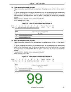
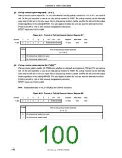
(3) Pull-up resistor option register B2 (PUB2)
Pull-up resistor option register B2 (PUB2) sets whether on-chip pull-up resistors on P20 to P26 are used or
not.
On the port specified to use an on-chip pull-up resistor by PUB2, the pull-up resistor can be internally used
only for the bits set in the input mode. No on-chip pull-up resistors can be used for the bits set in the output
mode regardless of the setting of PUB2. This also applies to cases when the pins are used for alternate
functions.
PUB2 is set with a 1-bit or 8-bit memory manipulation instruction.
RESET input sets PUB2 to 00H.
Figure 4-20. Format of Pull-Up Resistor Option Register B2
Symbol
PUB2
7
0
<6> <5> <4> <3> <2> <1> <0>
PUB26 PUB25 PUB24 PUB23 PUB22 PUB21 PUB20
Address
FF32H
After reset
00H
R/W
R/W
PUB2n
P2n on-chip pull-up resistor selection
(n = 0 to 6)
0
1
On-chip pull-up resistor not used
On-chip pull-up resistor used
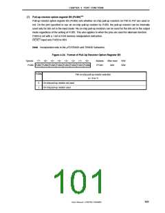
(4) Pull-up resistor option register B3 (PUB3)
Pull-up resistor option register B3 (PUB3) sets whether on-chip pull-up resistors on P30 to P33 are used or
not.
On the port specified to use an on-chip pull-up resistor by PUB3, the pull-up resistor can be internally used
only for the bits set in the input mode. No on-chip pull-up resistors can be used for the bits set in the output
mode regardless of the setting of PUB3. This also applies to cases when the pins are used for alternate
functions.
PUB3 is set with a 1-bit or 8-bit memory manipulation instruction.
RESET input sets PUB3 to 00H.
Figure 4-21. Format of Pull-Up Resistor Option Register B3
Symbol
PUB3
7
0
6
0
5
0
4
0
<3> <2> <1> <0>
PUB33 PUB32 PUB31 PUB30
Address
FF33H
After reset
00H
R/W
R/W
PUB3n
P3n on-chip pull-up resistor selection
(n = 0 to 3)
On-chip pull-up resistor not used
On-chip pull-up resistor used
0
1
User’s Manual U15075EJ1V0UM00
99

 NEC [ NEC ]