CHAPTER 4 PORT FUNCTIONS
4.2.3 Port 2
This is a 7-bit I/O port with an output latch. Port 2 can be specified in the input or output mode in 1-bit units by
using port mode register 2 (PM2). When using the P20 to P26 pins as input port pins, on-chip pull-up resistors can
be connected in 1-bit units by using pull-up resistor option register B2 (PUB2).
The port is also used as the serial interface I/O, buzzer output, and timer output.
This port is set in the input mode when the RESET signal is input.
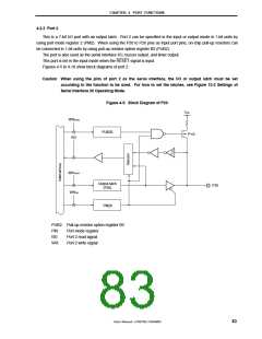
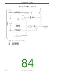
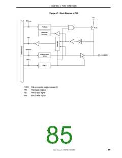
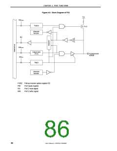
Figures 4-5 to 4-10 show block diagrams of port 2.
Caution When using the pins of port 2 as the serial interface, the I/O or output latch must be set
according to the function to be used. For how to set the latches, see Figure 12-2 Settings of
Serial Interface 20 Operating Mode.
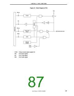
Figure 4-5. Block Diagram of P20
V
DD
WRPUB2
PUB20
P-ch
RD
WRPORT
Output latch
(P20)
P20
WRPM
PM20
PUB2: Pull-up resistor option register B2
PM:
RD:
WR:
Port mode register
Port 2 read signal
Port 2 write signal
User’s Manual U15075EJ1V0UM00
83

 NEC [ NEC ]