CHAPTER 4 PORT FUNCTIONS
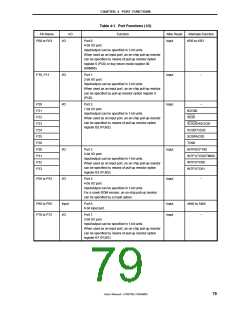
Table 4-1. Port Functions (1/2)
Pin Name
I/O
Function
After Reset
Input
Alternate Function
KR0 to KR3
P00 to P03
I/O
Port 0.
4-bit I/O port.
Input/output can be specified in 1-bit units.
When used as an input port, an on-chip pull-up resistor
can be specified by means of pull-up resistor option
register 0 (PU0) or key return mode register 00
(KRM00).
P10, P11
I/O
I/O
Port 1.
Input
Input
−
2-bit I/O port.
Input/output can be specified in 1-bit units.
When used as an input port, an on-chip pull-up resistor
can be specified by pull-up resistor option register 0
(PU0).
P20
P21
P22
P23
P24
P25
P26
P30
P31
P32
P33
Port 2.
−
7-bit I/O port.
BZO90
Input/output can be specified in 1-bit units.
When used as an input port, an on-chip pull-up resistor
can be specified by means of pull-up resistor option
register B2 (PUB2).
SS20
SCK20/ASCK20
SO20/TxD20
SI20/RxD20
TO90
I/O
I/O
Port 3.
Input
Input
INTP0/CPT90
INTP1/TO50/TMI60
INTP2/TO60
INTP3/TO61
4-bit I/O port.
Input/output can be specified in 1-bit units.
When used as an input port, an on-chip pull-up resistor
can be specified by means of pull-up resistor option
register B3 (PUB3).
P50 to P53
Port 5.
−
4-bit I/O port.
Input/output can be specified in 1-bit units.
For a mask ROM version, an on-chip pull-up resistor
can be specified by a mask option.
P60 to P65
P70 to P72
Input
I/O
Port 6.
Input
Input
ANI0 to ANI5
6-bit input port.
Port 7.
−
3-bit I/O port.
Input/output can be specified in 1-bit units.
When used as an input port, an on-chip pull-up resistor
can be specified by means of pull-up resistor option
register B7 (PUB7).
User’s Manual U15075EJ1V0UM00
79

 NEC [ NEC ]