CHAPTER 15 STANDBY FUNCTION
15.1.2 Register controlling standby function
The wait time after the STOP mode is released upon interrupt request until oscillation stabilizes is controlled with
the oscillation stabilization time select register (OSTS).
OSTS is set with an 8-bit memory manipulation instruction.
RESET input sets OSTS to 04H. However, it takes 215/fX, not 217/fX, after RESET input.
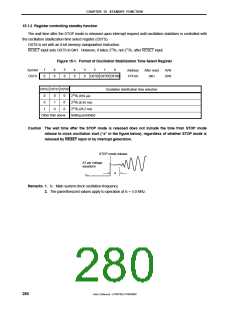
Figure 15-1. Format of Oscillation Stabilization Time Select Register
7
0
6
0
5
0
4
0
3
0
2
1
0
Symbol
OSTS
Address
FFFAH
After reset
04H
R/W
R/W
OSTS2 OSTS1 OSTS0
OSTS2 OSTS1 OSTS0
Oscillation stabilization time selection
212/f
215/f
217/f
X
X
X
(819 µs)
0
0
1
0
1
0
0
0
0
(6.55 ms)
(26.2 ms)
Other than above
Setting prohibited
Caution The wait time after the STOP mode is released does not include the time from STOP mode
release to clock oscillation start (“a” in the figure below), regardless of whether STOP mode is
released by RESET input or by interrupt generation.
STOP mode release
X1 pin voltage
waveform
a
V
SS
Remarks 1. fX: Main system clock oscillation frequency
2. The parenthesized values apply to operation at fX = 5.0 MHz.
280
User’s Manual U15075EJ1V0UM00

 NEC [ NEC ]