CHAPTER 12 SERIAL INTERFACE 20
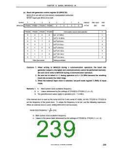
(c) Baud rate generator control register 20 (BRGC20)
BRGC20 is set with an 8-bit memory manipulation instruction.
RESET input sets BRGC20 to 00H.
Symbol
7
6
5
4
3
0
2
0
1
0
0
0
Address
FF73H
After reset
00H
R/W
R/W
BRGC20 TPS203 TPS202 TPS201 TPS200
n
1
2
3
4
5
6
7
8
TPS203 TPS202 TPS201 TPS200
3-bit counter source clock selection
0
0
0
0
0
0
0
0
0
0
0
0
1
1
1
1
0
0
1
1
0
0
1
1
0
1
0
1
0
1
0
1
fX
fX
fX
fX
fX
fX
fX
fX
/2 (2.5 MHz)
/22 (1.25 MHz)
/23 (625 kHz)
/24 (313 kHz)
/25 (156 kHz)
/26 (78.1 kHz)
/27 (39.1 kHz)
/28 (19.5 kHz)
Other than above
Setting prohibited
Cautions 1. When writing to BRGC20 during a communication operation, the baud rate
generator output is disrupted and communications cannot be performed normally.
Be sure not to write to BRGC20 during a communication operation.
2. Be sure not to select n = 1 during operation at fX = 5.0 MHz because the resulting
baud rate exceeds the rated range.
3. When the external input clock is selected, set port mode register 2 (PM2) to input
mode.
Remarks 1. fX: Main system clock oscillation frequency
2. n: Values determined by the settings of TPS200 to TPS203 (1 ≤ n ≤ 8)
3. The parenthesized values apply to operation at fX = 5.0 MHz.
If the internal clock is used as the serial clock for 3-wire serial I/O mode, set bits TPS200 to TPS203 to
set the frequency of the serial clock. To obtain the frequency to be set, use the following expression.
When an external clock is used, setting BRGC20 is not necessary.
fX
Serial clock frequency =
[Hz]
2n + 1
fX: Main system clock oscillation frequency
n: Values in the above table determined by the settings of TPS200 to TPS203 (1 ≤ n ≤ 8)
User’s Manual U15075EJ1V0UM00
239

 NEC [ NEC ]