CHAPTER 12 SERIAL INTERFACE 20
12.4.3 3-wire serial I/O mode
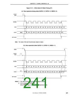
The 3-wire serial I/O mode is useful for connection of peripheral I/Os and display controllers, etc., which
incorporate a conventional clocked serial interface, such as the 75XL Series, 78K Series, and 17K Series.
Communication is performed using three lines: a serial clock (SCK20), serial output (SO20), and serial input
(SI20).
(1) Register setting
3-wire serial I/O mode settings are performed using serial operation mode register 20 (CSIM20),
asynchronous serial interface mode register 20 (ASIM20), and baud rate generator control register 20
(BRGC20).
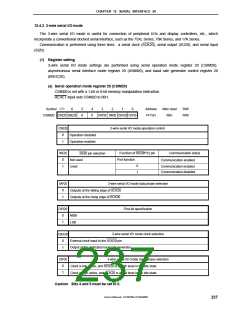
(a) Serial operation mode register 20 (CSIM20)
CSIM20 is set with a 1-bit or 8-bit memory manipulation instruction.
RESET input sets CSIM20 to 00H.
Symbol <7>
6
5
0
4
0
3
2
1
0
Address
FF72H
After reset
00H
R/W
R/W
CSIM20 CSIE20 SSE20
DAP20 DIR20 CSCK20 CKP20
CSIE20
3-wire serial I/O mode operation control
0
1
Operation disabled
Operation enabled
SSE20
Communication status
Function of SS20/P22 pin
Port function
SS20 pin selection
0
1
Not used
Used
Communication enabled
0
1
Communication enabled
Communication disabled
DAP20
3-wire serial I/O mode data phase selection
0
1
Outputs at the falling edge of SCK20
Outputs at the rising edge of SCK20
DIR20
First-bit specification
0
1
MSB
LSB
3-wire serial I/O mode clock selection
External clock input to the SCK20 pin
Output of the dedicated baud rate generator
CSCK20
0
1
CKP20
3-wire serial I/O mode clock phase selection
0
1
Clock is low active, and SCK20 is at high level in the idle state
Clock is high active, and SCK20 is at low level in the idle state
Caution Bits 4 and 5 must be set to 0.
User’s Manual U15075EJ1V0UM00
237

 NEC [ NEC ]