CHAPTER 10 8-BIT A/D CONVERTER (µPD789426 AND 789446 SUBSERIES)
(6) Noise prevention
To maintain a resolution of 8 bits, watch for noise to the AVDD and ANI0 to ANI5 pins. The higher the output
impedance of the analog input source, the larger the effect by noise. To reduce noise, attach an external
capacitor to the relevant pins as shown in Figure 10-10.
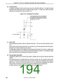
Figure 10-10. Analog Input Pin Treatment
If noise not lower than AVDD or not higher than
AVSS is likely to come to the AVDD pin, clamp
the voltage at the pin by attaching a diode with
a small V (0.3 V or lower).
F
VDD
AVDD
AVSS
C = 100 to 1,000 pF
VSS
(7) ANI0 to ANI5
The analog input pins (ANI0 to ANI5) are alternate-function pins. They are also used as port pins (P60 to
P65).
If any of ANI0 to ANI5 has been selected for A/D conversion, do not execute input instructions for the ports;
otherwise the conversion resolution may be reduced.
If a digital pulse is applied to a pin adjacent to the analog input pins during A/D conversion, coupling noise
may occur that prevents an A/D conversion result from being obtained as expected. Avoid applying a digital
pulse to pins adjacent to the analog input pins during A/D conversion.
(8) Interrupt request flag (ADIF0)
Changing the contents of A/D converter mode register 0 (ADM0) does not clear the interrupt request flag
(ADIF0).
If the analog input pins are changed during A/D conversion, therefore, the A/D conversion result and the
conversion end interrupt request flag may reflect the previous analog input immediately before writing to
ADM0 occurs. In this case, ADIF0 may already be set if it is read-accessed immediately after ADM0 is
write-accessed, even when A/D conversion has not been completed for the new analog input.
In addition, when A/D conversion is restarted, ADIF0 must be cleared beforehand.
User’s Manual U15075EJ1V0UM00
194

 NEC [ NEC ]