CHAPTER 10 8-BIT A/D CONVERTER (µPD789426 AND 789446 SUBSERIES)
10.4 8-Bit A/D Converter Operation
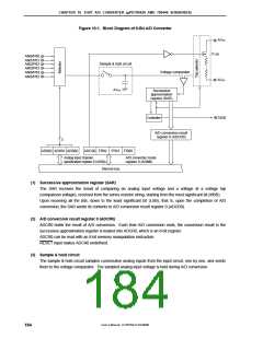
10.4.1 Basic operation of 8-bit A/D converter
<1> Select a channel for A/D conversion, using analog input channel specification register 0 (ADS0).
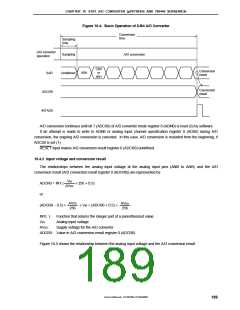
<2> The voltage supplied to the selected analog input channel is sampled using the sample & hold circuit.
<3> After sampling continues for a certain period of time, the sample & hold circuit is put on hold to keep the
input analog voltage until A/D conversion is completed.
<4> Bit 7 of the successive approximation register (SAR) is set. The series resistor string tap voltage at the
tap selector is set to half of AVDD.
<5> The series resistor string tap voltage is compared with the analog input voltage using the voltage
comparator. If the analog input voltage is higher than half of AVDD, the MSB of SAR is left set. If it is
lower than half of AVDD, the MSB is reset.
<6> Bit 6 of SAR is set automatically, and comparison shifts to the next stage. The next tap voltage of the
series resistor string is selected according to bit 7, which reflects the previous comparison result, as
follows:
• Bit 7 = 1: Three quarters of AVDD
• Bit 7 = 0: One quarter of AVDD
The tap voltage is compared with the analog input voltage. Bit 6 is set or reset according to the result of
comparison.
• Analog input voltage ≥ tap voltage: Bit 6 = 1
• Analog input voltage < tap voltage: Bit 6 = 0
<7> Comparison is repeated until bit 0 of SAR is reached.
<8> When comparison is completed for all of the 8 bits, a significant digital result is left in SAR. This value is
sent to and latched in A/D conversion result register 0 (ADCR0). At the same time, it is possible to
generate an A/D conversion end interrupt request (INTAD0).
Cautions 1. The first A/D conversion value immediately after A/D conversion has been started may be
undefined.
2. In standby mode, A/D converter operation is stopped.
User’s Manual U15075EJ1V0UM00
188

 NEC [ NEC ]