CHAPTER 8 WATCH TIMER
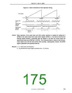
Figure 8-3. Watch Timer/Interval Timer Operation Timing
5-bit counter
0H
Overflow
Start
Overflow
Count clock
/29
f
W
Watch timer
interrupt
INTWT
Watch timer interrupt time (0.5 s)
Watch timer interrupt time (0.5 s)
Interval timer
interrupt
INTWTI
Interval
T
timer (T)
Caution When operation of the watch timer and 5-bit counter operation is enabled by setting bit 0
(WTM0) of the watch mode timer mode control register (WTM) to 1, the interval until the first
interrupt request (INTWT) is generated after the register is set does not exactly match the
specification made with WTM3 (bit 3 of WTM). This is because there is a delay of one 9-bit pre-
scaler output cycle until the 5-bit counter starts counting. Subsequently, however, the INTWT
signal is generated at the specified intervals.
Remarks 1. fW: Watch timer clock frequency
2. The parenthesized values apply to operation at fW = 32.768 kHz.
User’s Manual U15075EJ1V0UM00
175

 NEC [ NEC ]