CHAPTER 7 8-BIT TIMER
7.4.3 Operation as carrier generator
An arbitrary carrier clock generated by TM60 can be output in the cycle set in TM50.
To operate timer 50 and timer 60 as carrier generators, settings must be made in the following sequence.
<1> Disable operation of TM50 and TM60 (TCE50 = 0, TCE60 = 0).
<2> Disable timer output of TO50 and TO60 (TOE50 = 0, TOE60 = 0).
<3> Set count values in CR50, CR60, and CRH60.
<4> Set the operation mode of timer 50 and timer 60 to carrier generator mode (see Figures 7-4 and 7-5).
<5> Set the count clock for timer 50 and timer 60.
<6> Set remote control output to carrier pulse (RMC60 (bit 2 of carrier generator output control register 60
(TCA60)) = 0).
Input the required value to NRZB60 (bit 1 of TCA60) by program.
Input a value to NRZ60 (bit 0 of TCA60) before it is reloaded from NRZB60.
<7> Select either TO60 or TO61 as the timer output pin.
If TO60 is selected: Set P32 to the output mode (PM32 = 0), set the P32 output latch to 0, and set TOE60
to output enable (TOE60 = 1).
If TO61 is selected: Set P33 to the output mode (PM33 = 0), set the P33 output latch to 0, and set TOE61
to output enable (TOE60 = 1).
<8> Enable the operation of TM50 and TM60 (TCE50 = 1, TCE60 = 1).
The operation of the carrier generator is as follows.
<1> When the count value of TM60 matches the value set in CR60, an interrupt request signal (INTTM60) is
generated and output of timer 60 is inverted, which makes the compare register switch from CR60 to
CRH60.
<2> After that, when the count value of TM60 matches the value set in CRH60, an interrupt request signal
(INTTM60) is generated and output of timer 60 is inverted again, which makes the compare register switch
from CRH60 to CR60.
<3> The carrier clock is generated by repeating <1> and <2> above.
<4> When the count value of TM50 matches the value set in CR50, an interrupt request signal (INTTM50) is
generated. The rising edge of INTTM50 is the data reload signal of NRZB60 and is transferred to NRZ60.
<5> When NRZ60 is 1, a carrier clock is output from the TO60 pin (or the TO61 pin).
Cautions 1. TCA60 cannot be set with a 1-bit memory manipulation instruction. Be sure to use an 8-bit
memory manipulation instruction.
2. When setting the carrier generator operation again after stopping it once, reset NRZB60
because the previous value is not retained. In this case also a 1-bit memory manipulation
instruction cannot be used. Be sure to use an 8-bit memory manipulation instruction.
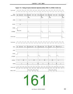
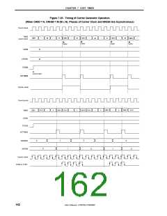
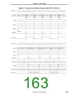
Figures 7-19 to 7-21 show the operation timing of the carrier generator.
160
User’s Manual U15075EJ1V0UM00

 NEC [ NEC ]