Please read CAUTION and Notice in this catalog for safety. This catalog has only typical specifications. Therefore you are requested
to approve our product specification or to transact the approval sheet for product specification, before your ordering.
P61E7.pdf 01.10.17
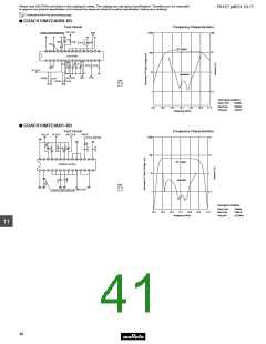
Lead Type CERAFILr Test Circuit and Characteristics Data
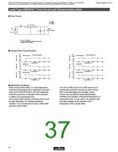
■ Test Circuit
(1) : Input
(2) : Output
(3) :Ground
(1) (2) (3)
R1
RF
Voltmeter
Rg
C
R2
S.S.G
Rg + R1 = R2 = 330Ω
C = 10pF (Including stray capacitance and input
capacitance of RF voltmeter.)
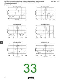
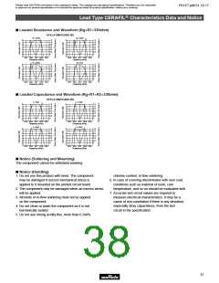
■ Temperature Characteristics
W40
W20
0
W40
W20
0
SFELA10M7GA00-B0
SFELA10M7HA00-B0
Center frequency
Center frequency
Y20
Y40
Y20
Y40
Y20
0
0
0
W20
W40
W40
W40
W60
W60
W60
W80
W80
W80
Y20
0
0
0
W20
W40
W40
W40
W60
W60
W60
W80
W80
W80
Temperature (˚C)
Temperature (˚C)
W2
W1
0
W2
W1
0
Insertion loss
Insertion loss
Y1
Y2
Y1
Y2
Y20
W20
Y20
W20
Temperature (˚C)
Temperature (˚C)
W40
W20
0
W40
W20
0
3dB Band width
3dB Band width
Y20
Y40
Y20
Y40
Y20
W20
Y20
W20
Temperature (˚C)
Temperature (˚C)
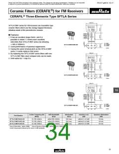
■ Matching Conditions
•When using ceramic filters, it is most important to
•The SFELA10M7 and SFTLA10M7 series are of
input/output symmetric structure so that in theory
there is no input/output directionality. Actual
circuits may use different input/output loading
conditions (for example, mismatched impedance) or
capacitance load. In such cases, the waveform will
be a little changed by the direction of the
10
match the input/output load to impedance 330 ohm
(only SFELA10M7DF00-B0 is 470 ohm matching).
Waveform symmetry is damaged when reactance
is added to the input/output load.
•Two ceramic filters directly connected can be used
for high selelctivity. For reducing waveform
variation, it is recommended to input a buffer AMP
between ceramic filters.
input/output of the ceramic filters.
36

 MURATA [ muRata ]