NMA 5V, 12V & 15V Series
Isolated 1W Dual Output DC/DC Converters
APPLICATION NOTES (continued)
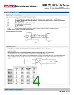
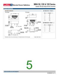
Ripple & Noise Characterisation Method
Ripple and noise measurements are performed with the following test configuration.
C1
C2
1μF X7R multilayer ceramic capacitor, voltage rating to be a minimum of 3 times the output voltage of the DC/DC converter
1ꢀμF tantalum capacitor, voltage rating to be a minimum of 1.5 times the output voltage of the DC/DC converter with an ESR of less
than 1ꢀꢀmꢁ at 1ꢀꢀ kHz
C3
R1
1ꢀꢀnF multilayer ceramic capacitor, general purpose
±5ꢀꢁ resistor, carbon film, ±1% tolerance
R2
5ꢀꢁ BNC termination
T1
3T of the coax cable through a ferrite toroid
RLOAD
Resistive load to the maximum power rating of the DC/DC converter. Connections should be made via twisted wires
Measured values are multiplied by 1ꢀ to obtain the specified values.
Differential Mode Noise Test Schematic
DC/DC Converter
OSCILLOSCOPE
Y INPUT
R2
C1 C2 C3
R1
T1
+
+
Input
Output
SUPPLY
-
-
R LOAD
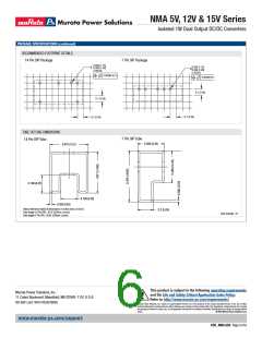
Output Ripple Reduction
By using the values of inductance and capacitance stated, the output ripple at the rated load is lowered to 5mV p-p max.
Component selection
Capacitor: It is required that the ESR (Equivalent Series Resistance) should be as low as possible, ceramic types are recommended.
The voltage rating should be at least twice (except for 15V output), the rated output voltage of the DC/DC converter.
Inductor: The rated current of the inductor should not be less than that of the output of the DC/DC converter. At the rated current, the DC resistance of the inductor
should be such that the voltage drop across the inductor is <2% of the rated voltage of the DC/DC converter. The SRF (Self Resonant Frequency) should be
>2ꢀMHz.
L
DC
Power
Source
Load
C
DC
Inductor
SMD
Capacitor
C, μF
L, μH
22
Through Hole
11R223C
11R1ꢀ±C
11R15±C
11R22±C
11R223C
11R±73C
11R15±C
11R22±C
11R223C
11R15±C
11R22±C
NMAꢀ5ꢀ5xC
NMAꢀ5ꢀ9xC
NMAꢀ512xC
NMAꢀ515xC
NMA12ꢀ5xC
NMA12ꢀ9xC
NMA1212xC
NMA1215xC
NMA15ꢀ5xC
NMA1512xC
NMA1515xC
82223C
821ꢀ±C
8215±C
8222±C
82223C
82±73C
8215±C
8222±C
82223C
8215±C
8222±C
2.2uF
ꢀ.±7uF
ꢀ.33uF
1uF
1ꢀꢀ
15ꢀ
22ꢀ
22
2.2uF
1uF
±7
15ꢀ
22ꢀ
22
ꢀ.33uF
1uF
2.2uF
ꢀ.33uF
2.2uF
15ꢀ
22ꢀ
www.murata-ps.com/support
KDC_NMA.G02 Page ± of 6

 MURATA [ muRata ]