NMA 5V, 12V & 15V Series
Isolated 1W Dual Output DC/DC Converters
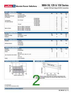
OUTPUT CHARACTERISTICS
Parameter
Conditions
Min.
Typ.
Max.
1
Units
W
Rated Power1
TA=-±ꢀ°C to 12ꢀ°C
See tolerance envelope
High VIN to low VIN
Voltage Set Point Accuracy
Line regulation
1.ꢀ
1ꢀ
9
6.5
6
5.5
2.6
2.3
1ꢀ
7
1.2
12.5
1ꢀ
7.5
7.ꢀ
1ꢀ
3.ꢀ
3.ꢀ
2ꢀ
%/%
5V output types
9V output types
12V output types
15V output types
5V output types
12V output types
15V output types
5V & 12V input
Load Regulation
1ꢀ% load to rated load
%
15V input
BW=DC to 2ꢀMHz, 5V output types
BW=DC to 2ꢀMHz, 9V output types
BW=DC to 2ꢀMHz, 12V output types
BW=DC to 2ꢀMHz, 15V output types
15
15
15
Ripple and Noise2
mV p-p
7.5
8
ISOLATION CHARACTERISTICS
Parameter
Isolation test voltage
Resistance
Conditions
Flash tested for 1 second
Viso= 1ꢀꢀꢀVDC
Min.
1ꢀꢀꢀ
Typ.
1ꢀ
Max.
Max.
Units
VDC
GΩ
GENERAL CHARACTERISTICS
Parameter
Conditions
Min.
Typ.
11ꢀ
1±ꢀ
9ꢀ
Units
kHz
5V input types
12V input types
15V input types
Switching frequency
TEMPERATURE CHARACTERISTICS
Parameter
Specification
Storage
Conditions
All output types
Min.
-±ꢀ
Typ.
Max.
85
Units
°C
-5ꢀ
13ꢀ
ꢀ5ꢀ5, 12ꢀ5
33
28
26
17
ꢀ5ꢀ9, ꢀ512, ꢀ515, 12ꢀ9, 1212, 1215
Case Temperature above ambient
Cooling
15ꢀ5
1512, 1515
Free air convection
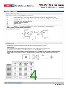
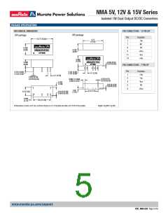
TEMPERATURE DERATING GRAPH
TOLERANCE ENVELOPE
1.5
+1ꢀ%
+5%
VNOM
+2.5%
85°C
1.ꢀ
-2.5%
-7.5%
ꢀ.5 Safe Operating Area
12ꢀ°C
15ꢀ
ꢀ
1ꢀꢀ
75
Output Load Current (%)
1ꢀ 25
5ꢀ
-±ꢀ
1ꢀꢀ
ꢀ
5ꢀ
Ambient Temperature (°C)
The voltage tolerance envelope shows typical load regulation characteristics for this
product series. The tolerance envelope is the maximum output voltage variation due to
changes in output loading.
1. See derating graph.
2. See Ripple & Noise characterisation method.
www.murata-ps.com/support
KDC_NMA.G02 Page 2 of 6

 MURATA [ muRata ]